User’s Manual of GSD-800S / GSD-802S / GSD-802PS
That is, although the VLAN 2 members: Port-1 to Port-3 and VLAN 3 members: Port-4 to Port-6 also belong to VLAN 1.
But with different PVID settings, packets form VLAN 2 or VLAN 3 is not able to access to the other VLAN.
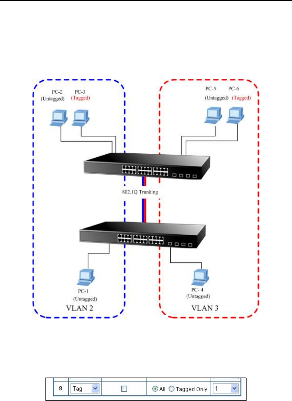
4.5.3.3 VLAN Trunking between two 802.1Q aware switch
The most cases are used for “Uplink” to other switches. VLANs are separated at different switches, but they need to
access with other switches within the same VLAN group. The screen in Figure-20 appears.
Figure 4-20 802.1Q Trunking with other VLAN aware device
About the VLAN ports connect to the hosts, please refer to 4.5.3.1 and 4.5.3.2 examples. The following steps will focus on
the VLAN Trunk port configuration.
1. Specify Port-8 to be the 802.1Q VLAN Trunk port, and the Trunking port must be a Tagged port while egress. The
Port-8 configuration as the following screen in Figure 4-21.
Figure 4-21 The configuration of VLAN Trunk port
2. Assign the VLAN Trunk Port to be the member of each VLAN – which wants to be aggregated. At this sample, add
Port-8 to be VLAN 2 and VLAN 3 member port.


