


User’s Manual of SGSD-1022 / SGSD-1022P
SGSW-2840 / SGSW-2840P
168
4.7.2 MSTP
4.7.2.1 Configuring Multiple Spanning Trees
MSTP generates a unique spanning tree for each instance. This provides multiple pathways across the network, thereby
balancing the traffic load, preventing wide-scale disruption when a bridge node in a single instance fails, and allowing for faster
convergence of a new topology for the failed instance.
By default all VLANs are assigned to the Internal Spanning Tree (MST Instance 0) that connects all bridges and LANs within the
MST region. This switch supports up to 9 instances. You should try to group VLANs which cover the same general area of your
network. However, remember that you must configure all bridges within the same MSTI Region with the same set of instances,
and the same instance (on each bridge) with the same set of VLANs. Also, note that RSTP treats each MSTI region as a single
node, connecting all regions to the Common Spanning Tree.
To use multiple spanning trees:
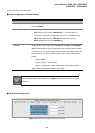
1. Set the spanning tree type to MSTP (STA Configuration).
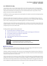
2. Enter the spanning tree priority for the selected MST instance (MSTP VLAN Configuration).
3. Add the VLANs that will share this MSTI (MSTP VLAN Configuration).
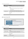
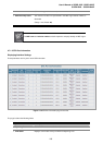
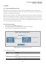
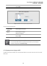
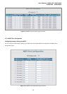
Figure 4-7-8 MSTP VLAN Configuration page screenshot
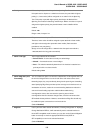
The page includes the following fields:
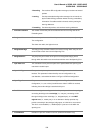
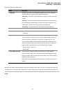
Object Description
• MST Instance
Instance identifier of this spanning tree.
(Default: 0)
• Priority
The priority of a spanning tree instance.
Range: 0-61440 in steps of 4096; Options: 0, 4096, 8192, 12288, 16384, 20480,