


E – 11
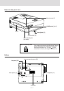
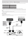
VIDEO IN
PC CONTROL
REMOTE CONTROL
AUDIO OUT
RGB OUTRGB IN AUDIO IN
VIDEOS-VIDEO
IN
OUT
L/MONO·AUDIO·R
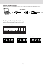
VIDEO IN
PC CONTROL
REMOTE CONTROL
AUDIO OUT
RGB OUTRGB IN AUDIO IN
VIDEOS-VIDEO
IN
OUT
L/MONO·AUDIO·R
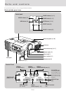
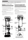
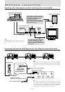
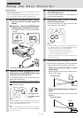
Connecting video equipment
You can connect a document camera, VCR, laser disc player, and DVD player, etc.
Connecting to the VIDEO IN VIDEO/S-
VIDEO jacks
You can connect up to two pieces of video equipment to the VIDEO
IN jacks following the illustration below. Two types of connections
can be made. Connect either using the cables indicated in dotted
lines or those in gray as shown in the drawing below.
• You can switch the input source (picture) to VIDEO or S-VIDEO
even if you connect more than one piece of equipment. S-VIDEO
connection provides more vivid color and higher resolution
compared to VIDEO connection.
• You can output the sound of one component through the unit
speaker even when two components are connected.
Before connecting
• Turn off the components that are to be connected.
• The unit and computer will be turned on in “Using the Data
Projector” on page 16. Do not turn on either the computer or unit
until you read this section.
• Please also refer to the manual of the video component to be
connected.
VCR, document camera, etc.
To audio
output Left/
Right jacks
To video
output jack
Audio video cable
(supplied)
The unit
terminal panel
Laser disc player, DVD player,
document camera, etc.
S-video cable
(supplied)
To audio
output Left/
Right jacks
To video
output jack
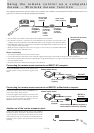
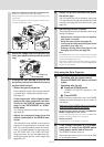
Connecting video equipment that has
the component video signal (YCbCr)
output jacks to the RGB IN connector
You can also connect the video component to the RGB IN connec-
tor, if the video component has the component video (YCbCr)
signal jacks. This connection provides better picture quality than
the connections on the left column.
• You can switch the input source to VIDEO, S-VIDEO, or RGB.
• The AUDIO IN jack is for equipment connected to the RGB IN
connector.
Before connecting
• Turn off the components that are to be connected.
• The unit and computer will be turned on in “Using the Data
Projector” on page 16. Do not turn on either the computer or unit
until you read this section.
• Please also refer to the manual of the video component to be
connected.
DVD player, laser disc player,
document camera, etc.
To YCbCr
signal output
jacks
To audio
output jacks
Mini-plug/pin-plug
adapter cable (not
supplied)
YCbCr signal jacks/
RGB connector
adapter cable
(optional)
The unit
terminal panel
Plug the cable terminal into the RGB
connector securely then tighten the screws.
Connections