


MGC-50/MGC-100 Getting Started Guide
2-3
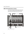
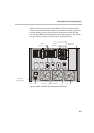
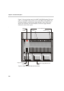
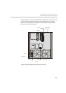
Figure 2-2 shows the rear panel of the MGC-100. The rear panel provides
access to the network I/O card connectors. I/O cards are inserted via the rear
panel. In addition, the rear panel houses the main power switch, AC inlet,
fans, the fuse, additional communications ports and alarm ports. The Alarms
port provides dry contacts for critical, major, and minor alarms.
Figure 2-2: MGC-100 Rear Panel with External Connectors
LANALARMSCOM 1COM
MUSIC
LINE IN
AC Inlet
Main Switch
and Circuit Breaker
Main Control
Module Cover
Network
Connectors
RS232
Connectors
Fan
Dry Contacts RJ45 Connector
Slot A
10/100 Mbits