


Chapter 2 - Hardware Description
2-8
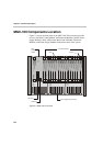
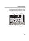
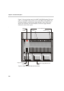
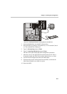
MGC Unit Components
The following table describes the MGC components. A more detailed
description is found in the MGC-50/MGC-100 Hardware & Installation
Manual.
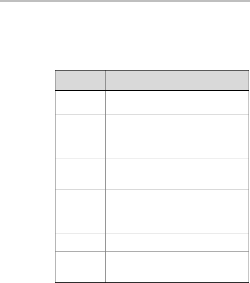
Table 2-1: MGC Component Description
MGC
Component
Description
Control Module The Main Control Module performs the conference setup
and termination and resource allocation in both the
MGC-100 and the MGC-50.
Backplane The backplane is an electronic circuit board into which
The Network Interface Module, the Main Control Module,
Functional Modules, and I/O cards are plugged so the
various modules can communicate with each other. The
Backplane is based on the “universal slot” concept, where
any card can be inserted in any slot.
Power Plane The Power Plane is a conducting layer providing power to
the components. It is part of the Backplane and is
designed to accommodate hot swapping of power
supplies.
Power Supply
Modules
The Power Supply Module is located underneath the Main
Control Module and the Functional Modules and is
connected to the backplane. It provides power to the
Backplane by means of a power bus. Both MGC units
(MGC-100 and MGC-50) operate at 100-240 volts AC 50/
60 Hz.
Fans Three (MGC-100) or two (MGC-50) fans are mounted at
the bottom of the rear panel.
Alarms Port In the MGC-100 an Alarms port is located on the Main
Control Module. The dry contacts on the rear panel of the
MGC-100 are for connecting to the customer’s alarm
system.