


Chapter 2 - Hardware Description
2-4
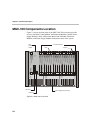
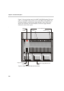
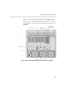
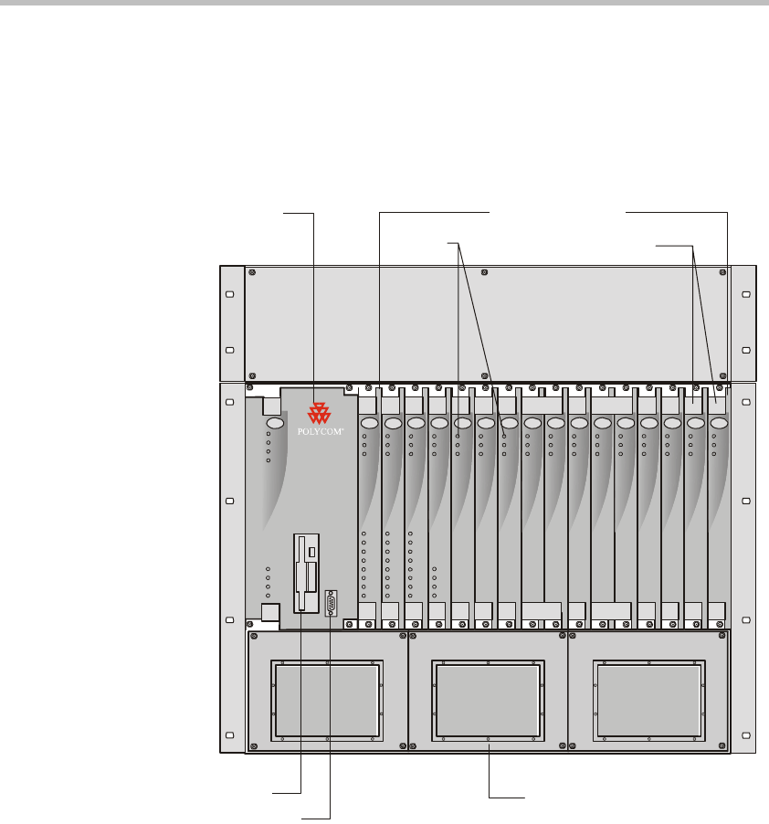
Figure 2-3 shows the front panel of the MGC-100 NEBS Standard. The front
panel, as in the MGC-100, provides access to the Main Control Module, the
Functional Modules, and the Power Supply Modules. Status LEDs on the
Main Control Module, Functional Modules, and Power Supply Modules
indicate the status of the system.
.
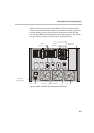
Figure 2-3: MGC-100 NEBS Standard Front Panel
Power Supply Module Cover
Floppy Disk Drive
COM Port
Power
L1
L2
L3
Critical
Major
Minor
L0
CONT
Line A
Line B
Stb y
Fail
Active
Stb y
Fail
Active
Stby
Fail
Active
Stby
Fail
Active
Stb y St by
Fail Fail
Active Active
Stby
Fail
Active
Stb y St by
Fail Fail
Active Active
Stby
Fail
Active
Stb y St by
Fail Fail
Active Active
Stby
Fail
Active
Stb
y
Fail
A
ctive
Stby
Fail
Active
NET-E 1
MUX MUX DATA DATA VIDEO VIDEO VIDEO AUDIOVIDEO AUDIO
Stby
Fai l
A
ctiv e
A
UDIO
A
UDIO
Line 6
Line 7
Line 8
Line 3
Line 4
Line 5
Line 1
Line 2
Line 6
Line 7
Line 8
Line 3
Line 4
Line 5
Line 1
Line 2
Line 6
Line 7
Line 8
Line 3
Line 4
Line 5
Line 1
Line 2
NET-8NET-8 NET-8
Ejectors
LEDs
Main
Control
Module
Functional Modules
MGC-100