


Chapter 8 - MGC-25 Management Tools
8-11
For additional information, see the MGC Manager Administrator’s Guide,
Chapter 4.
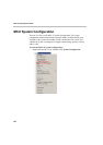
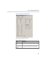
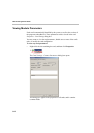
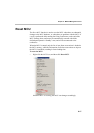
The configuration of each card can be checked and for specific cards,
modified if required. Any operator can view the card’s configuration settings.
Only an operator defined as Superuser can modify the configuration settings
of a card.
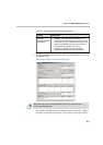
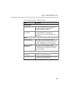
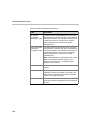
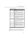
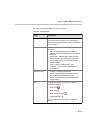
Table 8-5: MCU's Cards Status
Field Description
Slot Displays the slot icon and number; a white icon
indicates an empty slot and a green icon indicates
an occupied slot.
Type Displays the type of card that occupies the slot. The
following card types are available, as listed in
Table 8-4.
Clock This field is valid only for Net-2 cards. It indicates
which Network card/span is used as the Master
Clock.
Configured Clock Indicates which ISDN Network card was configured
as the Primary network interface (for clocking).
Changes take effect and are updated during the next
MCU reset or power up.
Status Indicates the card status: Normal or Faulty.
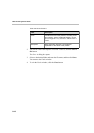
Occupied Units Indicates the units that are currently used to run
conferences by displaying their sequential number
on the card. For example, 1, 6 indicates that two
units, unit # 1 and unit # 6 are used to run
conferences.
Faulty Units Indicates whether there are units on the card that
are faulty and the displays the sequential number of
the faulty unit.
Disabled Units Indicates the units that were disabled by the
operator. The units may be disabled using the card's
right-click menu.
Num Units Indicates the total number of units available for each
module.