


INSTALLATION
EATON Powerware
®
Energy Management System (EMS) Upgrade Kit User’s Guide S 164201724 Rev 1 www.powerware.com
14
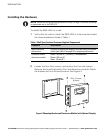
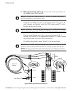
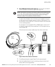
3. Plan the wiring route from the electronics module to the monitored
breaker panel(s). See Table 2 through Table 4, Figure 5, and use the
following guidelines.
S Mount the electronics module within 3.05m (10 ft) of a
disconnect device.
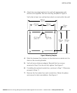
S If installing conduit (not supplied), plan for adequate conduit
routing. Follow National Electrical Code
®
(NEC
®
) and local
guidelines for conduit length and bending radius. Installed width
of the EMS−UGK with both conduit boxes is 633 mm (24.9").
Remove conduit box hole plugs as needed for conduit.
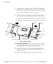
S Follow NEC and local guidelines for filling wiring space and
maintaining the thermal performance of the equipment.
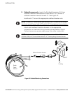
S Plan the location and installation of the CTs and wire taps to
allow for adequate bending radius of wiring. If necessary,
support the CTs to avoid undue strain on wiring.
Table 2. Current Transformer Sizing
Type of CT Rating
CT Dimensions
(W
H D)
Lead Length
Maximum Wire Insulation
Outside Diameter
Branch CT 75A 25.4 38.1 25.4 mm
(1.0"
1.5" 1.0")
0.91m (36.0") 10.16 mm (0.40")
Branch CT
(separate accessory)
100A 41.0 51.0 30.0 mm
(1.6"
2.0" 1.2")
1.00m (39.4") 16.00 mm (0.63")
Main CT (phases A,
B, C, and Neutral)
400A 96.0 100.0 46.0 mm
(3.8"
3.9" 1.8")
0.91m (36.0") 22.86 mm (0.90")
Input Ground CT 100A 66.0 70.0 33.0 mm
(2.6"
2.8" 1.3")
0.91m (36.0") 15.24 mm (0.60")
Subfeed CT
(separate accessory)
400A 96.0 100.0 46.0 mm
(3.8"
3.9" 1.8")
0.91m (36.0") 22.86 mm (0.90")
Table 3. Wire Tap Sizing
Housing Color Wire Size
Blue 0.75–2.5 mm
2
(18–14 AWG)
Yellow 4.0 mm
2
(12 AWG)
NOTE Use wire taps ONLY on thermoplastic insulation (PVC).