


INSTALLATION
EATON Powerware
®
Energy Management System (EMS) Upgrade Kit User’s Guide S 164201724 Rev 1 www.powerware.com
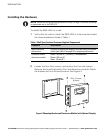
18
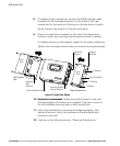
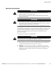
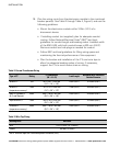
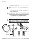
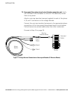
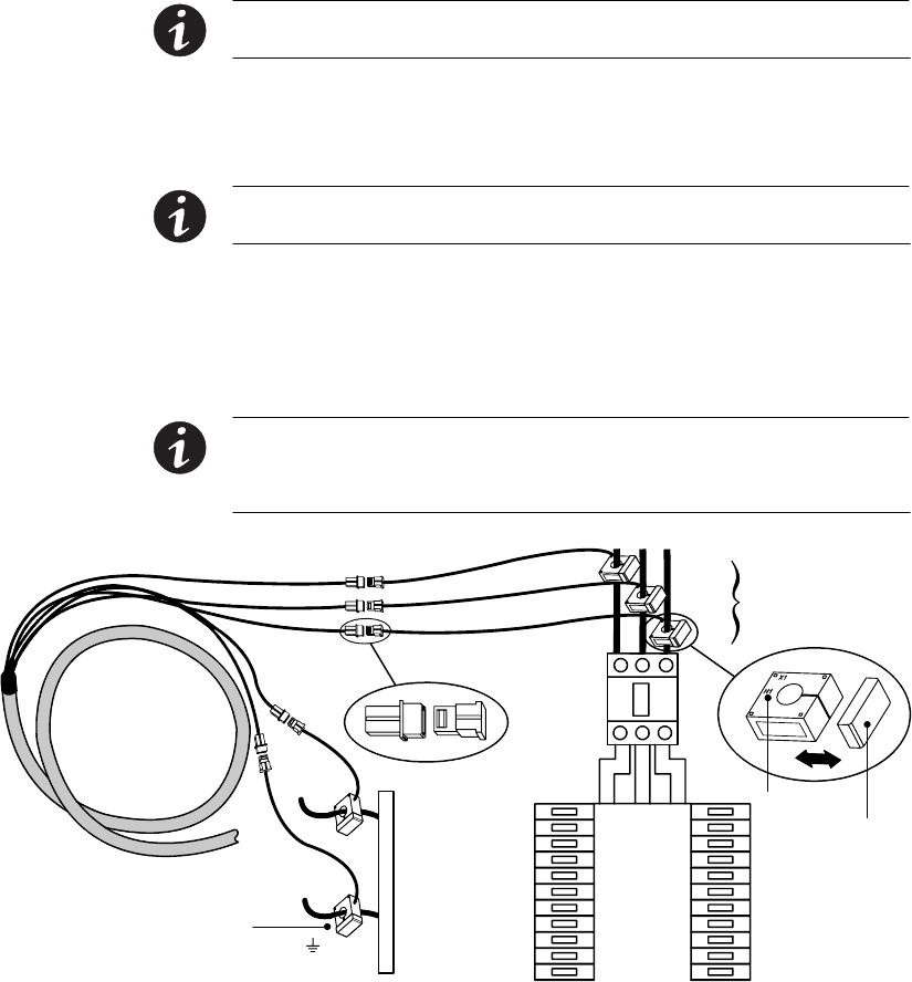
5. Main input monitoring option only. Connect the main input harness to
the breaker panel (see Figure 8):
NOTE If you prefer not to install the Neutral CT, the EMS−UGK software can perform an
approximate calculation of the Neutral CT values.
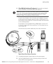
Install the four 400A main CTs to the breaker panel wiring for A, B,
and C phases, and Neutral. Install the 100A input ground CT to the
breaker panel ground wiring.
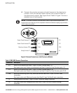
NOTE To install a CT, remove the cap, open the body of the CT to insert the wire through
the slit, and reinstall the cap. Install all CTs with the H1" lettering facing the same direction.
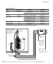
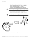
Connect each labeled lead on the main input harness (A, B, C,
Neutral, and Ground) to the appropriate installed CT. Coil and secure
any excess cable away from other conductors.
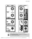
If installing dual panels, repeat Step 5 for the second panel.
NOTE Verify all installed main input monitoring wiring is correct and follows NEC and local
guidelines. Verify all CTs are installed with their H1" lettering facing the same direction.
NOTE The input ground CT will provide valid readings only in an isolated ground system.
C
C
B
A
Neutral
Ground
100A
400A
400A
Main Input
Harness
H1"
Lettering
Input Ground CT
Main CT
Cap
Figure 8. Main Input Harness Connections