


INSTALLATION
EATON Powerware
®
Energy Management System (EMS) Upgrade Kit User’s Guide S 164201724 Rev 1 www.powerware.com
16
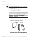
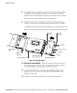
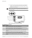
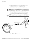
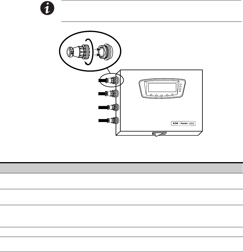
4. Connect the circular connector of each harness to the electronics
module. Verify the harness label matches the connector label on
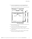
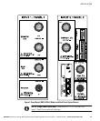
the electronics module. See Figure 6 and Table 5. Figure 7 shows a
detailed view of both panels.
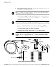
NOTE To connect a harness to the electronics module, align the polarizing keys and
keyways and insert the plug into the receptacle. Rotate the attached coupling ring clockwise
until it snaps into position.
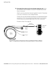
CT1
CT2
CTM
V1
CT1
CT2
CTM
V2
Branch Circuit Harness CT1
Branch Circuit Harness CT2
Main Input Harness CTM
Voltage Harness V1
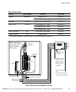
Figure 6. Harness Connections at the Electronics Module
Table 5. EMS−UGK Harness Connections
Connection Description
CT1 Branch circuit harness from Panel 1 / Input 1 to Panel 1 breaker poles 1–21.
Dual panel option only. Branch circuit harness from Panel 2 / Input 2 to Panel 2 breaker poles 1–21.
CT2 Branch circuit harness from Panel 1 / Input 1 to Panel 1 breaker poles 22–42.
Dual panel option only. Branch circuit harness from Panel 2 / Input 2 to Panel 2 breaker poles 22–42.
CTM Main input monitoring option only. Main input harness from Panel 1 / Input 1 to Panel 1 main
connections.
Dual panel option only. Main input harness from Panel 2 / Input 2 to Panel 2 main connections.
V1 Voltage harness from Panel 1 / Input 1 to Panel 1 reference voltage connection.
V2 Dual panel option only. Voltage harness from Panel 2 / Input 2 to Panel 2 reference voltage
connection.