


OPERATION
EATON Powerware
®
Energy Management System (EMS) Upgrade Kit User’s Guide S 164201724 Rev 1 www.powerware.com
38
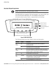
Control Panel Functions
NOTE Use this section only if the optional display is installed.
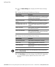
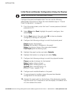
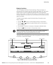
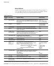
The EMS−UGK has a graphical LCD with backlight, four status LEDs, and
five control buttons (see Figure 18). The display provides useful
information about system events, measurements, and settings.
PRESS ANY KEY TO CONTINUE
Power On (green)
Overload (yellow)
No function (always off)
Alarm (red)
Control Buttons for the LCD Menu Options
Figure 18. EMS−UGK Display
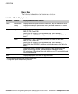
The following table shows the indicator status and description.
Indicator Status Description
ON
Green
On The product on which the EMS−UGK is installed is
operating normally.
Off The product on which the EMS−UGK is installed is turned
off and will not turn on automatically.
O/L
Yellow
On One or more phases is in overload, or there is an alarm or
warning for neutral overload, ground overload, main panel
breaker overload, or panel breaker overload.
OFF Off Not applicable for the EMS−UGK.
AL
Red
Flashing There is a new or cleared EMS−UGK alarm condition. See
Troubleshooting" on page 61 for additional information.
To silence the horn, press any button.
On An acknowledged alarm condition exists.