


OPERATION
EATON Powerware
®
Energy Management System (EMS) Upgrade Kit User’s Guide S 164201724 Rev 1 www.powerware.com
45
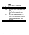
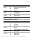
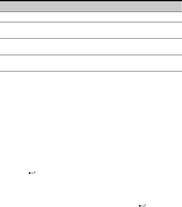
4. On the PANEL CONFIG screen, set the panel’s meter settings:
Default Range Meter Setting Description
3 3 PHASES Number of phases
42 0–42
(even numbers)
BREAKERS* Number of subfeed breakers in
the panel, times 3
100 0–1200 RATING Subfeed breaker rating (in amps)
(see Note 1)
STANDARD STANDARD
COLUMN
PNL LAYOUT Panel layout
(see Note 2)
* For example, if the panel has 6 subfeed breakers, set the BREAKERS value to 18.
NOTE 1 Setting the panel breaker rating to 0 silences all main panel breaker
alarms and zeroes the panel percent current levels.
NOTE 2 Changing panel layout erases all branch circuit breaker configurations.
To reset all values on the screen to defaults, set the RESET value to
YES.
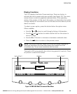
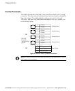
5. Select OK, the panel number (PNL), then SCHEDULE.
On the PANEL SCHEDULE screen, each subfeed breaker displays
as a group of three phases.
6. Select the
button to return to the PANEL screen.
7. Repeat Steps 3 to 6 for each panel containing subfeed breakers to
configure.
8. When all panel configuration is complete, select the
button
repeatedly to reach the main menu.
9. If all configuration is complete, save your changes by pressing the
Reset button on the Power Xpert Gateway Card in the X−Slot
communication bay. (The card automatically resets after five
minutes.) Otherwise, continue to the following section,
Configuring Branch Circuit Breakers."