


COMMUNICATION
EATON Powerware
®
Energy Management System (EMS) Upgrade Kit User’s Guide S 164201724 Rev 1 www.powerware.com
50
Installing Communication Features
To install the communication options and control terminals:
1. Install and connect the appropriate cable(s).
See the following section, Communication Options," or Control
Terminals" on page 52 for detailed information.
2. Route and tie the cable(s) out of the way.
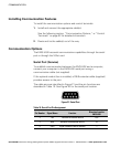
Communication Options
The EMS−UGK has serial communication capabilities through the serial
port or through the X−Slot card.
Serial Port (Service)
To establish communication between the EMS−UGK and a computer,
connect your computer to the EMS−UGK serial port using a
communication cable (not supplied).
If the optional conduit box is installed, a DB−9 extender cable (supplied)
provides access to the port.
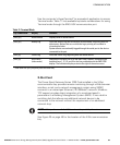
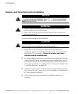
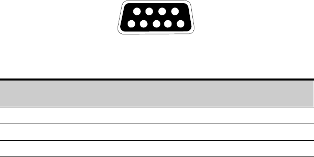
The cable pins are identified in Figure 21 and the pin functions are
described in Table 10. See Figure 20 for the serial port location.
3
8
7
9
1
6
245
Figure 21. Serial Port
Table 10. Serial Port Pin Assignment
Pin Number Signal Name Function
Direction from the
EMS−UGK
2 TxD Transmit to external device Out
3 RxD Receive from external device In
5 GND Signal common (tied to chassis) Ċ