


INSTALLATION
EATON Powerware
®
Energy Management System (EMS) Upgrade Kit User’s Guide S 164201724 Rev 1 www.powerware.com
19
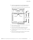
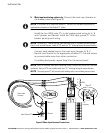
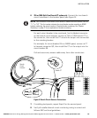
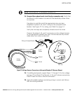
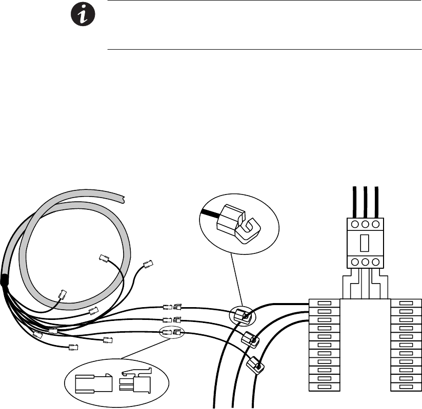
6. 75A or 100A Split−Core Branch CT option only. Connect the two branch
circuit harnesses to the breaker panel (see Figure 9):
NOTE Each connector on the branch circuit harness is labeled with two numbers, such as
1/1" or 5/3." The first number indicates the circuit breaker number according to NEMA
breaker numbering; the second number is Standard breaker numbering. See Breaker
Numbering" on page 37 for an explanation of breaker numbering.
For each circuit breaker to be monitored, find its labeled connector
on the branch circuit harness, connect a 75A or 100A branch CT to
the connector, then install the CT around the output wire connected
to the matching breaker.
For example, for circuit breaker 05 in a NEMA panel, connect a CT
to harness connector 5/3, then install the CT on the output wire for
circuit breaker 05.
Coil and secure any excess cable away from other conductors.
5/3
Breaker 05
Branch
Circuit
Harness
Branch CT
Figure 9. Branch Circuit Harness Connections
7. If installing dual panels, repeat Step 6 for the second panel.
8. Verify all installed branch circuit monitoring wiring is correct and
follows NEC and local guidelines.