


DESCRIPTION:
DATE:
DRAWING NO:
2of4
INSTALLATION NOTES
SHEET:
REVI SI ON:
C
164201177---1
041500
A --- 3
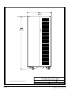
Po werware 9315 Maintenance Bypass Module 30---160kV A
164201177 Rev. C 041500
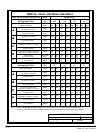
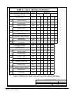
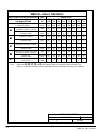
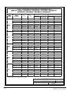
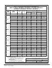
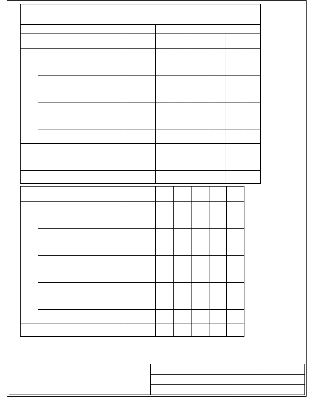
Table A- -2. Ratings & External Wiring Requirements for Powereware 9315
M B M 3 0 --- 1 6 0
kVA, 480:480VAC/600:600VAC
Rating and External Wiring Requirement
Units Rating 60 Hz
Basic unit rating at
0.8 lagging PF load
KVA
KW
160
128
130
104
100
80
UPS Input Voltage/Bypass Input
UPS Output Voltage
VOLTS
VOLTS
480
480
600
600
480
480
600
600
480
480
600
600
A
AC Input to M aint enance Bypass
(3) Phas es , ( 1) G ro und
AMPS 192 153 156 125 120 96
A
Conduct o r S i ze
Number per Phase
AWG/MCM
(each)
300
(1)
300
(1)
300
(1)
300
(1)
300
(1)
300
(1)
B
AC Input to UPS Bypass
(3) Phases, (1) Ground
AMPS 192 153 156 125 120 96
B
Conduct o r S i ze
Number per Phase
AWG/MCM
(each)
300
(1)
300
(1)
300
(1)
300
(1)
300
(1)
300
(1)
C
AC Output to Critical Load
(3) Phases, (1) Neutral, (1) Ground
AMPS 192 153 156 125 120 96
C
Conduct o r S i ze
Number per Phase
AWG/MCM
(each)
300
(1)
300
(1)
300
(1)
300
(1)
300
(1)
300
(1)
D
UPS / PTC Output to M BM Cabinet (MI S )
(3) Phas es , (1 ) Neut ral, ( 1) G ro und
AMPS 192 153 156 125 120 96
D
Conduct o r S i ze
Number per Phase
AWG/MCM
(each)
300
(1)
300
(1)
300
(1)
300
(1)
300
(1)
300
(1)
E
Control Wiring to U PS
(2) Conductors
VOLTS
AMPS
120
1
120
1
120
1
120
1
120
1
120
1
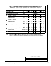
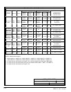
Basic unit rating at
0.8 lagging PF load
KVA
KW
80
64
65
52
50
40
40
32
30
24
UPS Input Voltage/Bypass Input
UPS Output Voltage
VOLTS
VOLTS
480
480
480
480
480
480
480
480
480
480
A
AC Input to M aint enance Bypass
(3) Phas es , ( 1) G ro und
AMPS 96 78 60 48 36
A
Conduct o r S i ze
Number per Phase
AWG/MCM
(each)
1
(1)
1
(1)
1
(1)
1
(1)
1
(1)
B
AC Input to UPS Bypass
(3) Phases, (1) Ground
AMPS 96 78 60 48 36
B
Conduct o r S i ze
Number per Phase
AWG/MCM
(each)
1
(1)
1
(1)
1
(1)
1
(1)
1
(1)
C
AC Output to Critical Load
(3) Phases, (1) Neutral, (1) Ground
AMPS 96 78 60 48 36
C
Conduct o r S i ze
Number per Phase
AWG/MCM
(each)
1
(1)
1
(1)
1
(1)
1
(1)
1
(1)
D
UPS / PTC Output to M BM Cabinet (MI S )
(3) Phas es , (1 ) Neut ral, ( 1) G ro und
AMPS 96 78 60 48 36
D
Conduct o r S i ze
Number per Phase
AWG/MCM
(each)
1
(1)
1
(1)
1
(1)
1
(1)
1
(1)
E
Control Wiring to U PS
(2) Conductors
VOLTS
AMPS
120
1
120
1
120
1
120
1
120
1
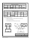
Note: Callout letters A, B, C, D,and E Map to drawing 164201177---4 (Reverse Tra ns fer Connection) and
164201177---7 (Parallel Connection). Read and understand the notes on drawings when planning your installation.