


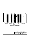
A --- 9
Po werware 9315 Maintenance Bypass Module 30---160kV A
164201177 Rev. C 041500
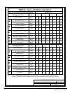
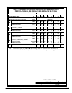
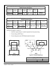
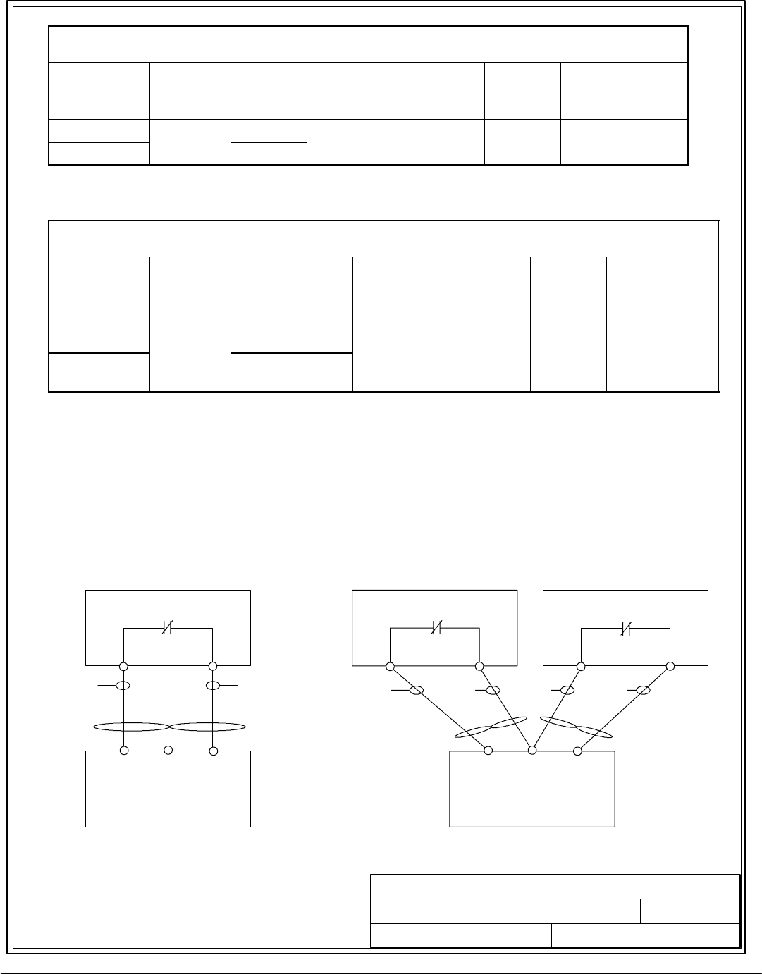
Table C--2. Control Wiring Requirements and Terminati on Requirement for
Reverse Transfer (RT) System.
Connecting Point
in MBM Cabinet
Size of
Pressure
Termination
(lb-in)
Connection
Point in UPS
Size of
Pressure
Termination
(lb-in)
Recommended
Wire Size
Maximum
Voltage and
Current
Remarks
TB1 --- 12
#18---#8
TB6 --- 1
#18---#8
#
1
8
#
1
4
120
V
A
C See Fi
g
1.
TB1 --- 14
#
1
8
#
8
(55)
TB6 --- 2
#
1
8
#
8
(55)
#18---#14
1
2
0
V
A
C
1.0A
S
e
e
F
i
g
1
.
(Twisted Pair)
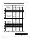
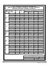
Table C--3. Control Wiring Requirements and Terminati on Requirement for
Parallel Redundant System.
Connecting Point
in MBM Cabinet
Size of
Pressure
Termination
(lb-in)
Connection Point
in UPS
Size of
Pressure
Termination
(lb-in)
Recommended
Wire Size
Maximum
Voltage and
Current
Remarks
TB1 --- 12
TB1 --- 13
#18---#8
TB6 --- 1 (UP S1)
TB6 --- 1 (UP S2)
#18---#8
#
1
8
#
1
4
120V
A
C See Fi
g
2.
TB1 --- 13
TB1 --- 14
#
1
8
#
8
(55)
TB6 --- 2 (UP S1)
TB6 --- 2 (UP S2)
#
1
8
#
8
(55)
#18---#14
1
2
0
V
A
C
1.0A
S
e
e
F
i
g
2
.
(Twisted Pair)
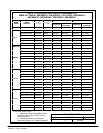
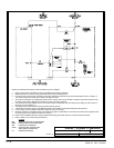
NOTES FOR TABLES C--2 AND C--3:
· Install the co pper wiring in a conduit s eparate from the power wiring.
· Control wiring is NEC Cl ass 1.
· Control wiring from each U PS Module should be twisted.
DESCRIPTION:
DATE:
DRAWING NO:
2of2
SHEET:
REVI SI ON:
C
041500
164201177---1
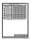
INSTALLATION NOTES
UPS
MBM
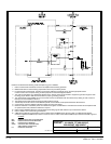
TB1
TB6
--- 1 --- 2
--- 12 --- 13 --- 14
K3
Twist Pair
BLK WHT
UPS1
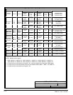
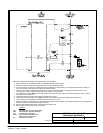
MBM
TB1
TB6
--- 1 --- 2
--- 12 --- 13 --- 14
K3
Twist Pair
BLK WHT
UPS2
TB6
--- 1 --- 2
K3
BLKWHT
Twist Pair
Figure 1. (Reverse Transfer)
Figure 2 . (Parallel Redundant)