


DESCRIPTION:
DATE:
DRAWING NO:
3of4
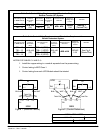
INSTALLATION NOTES
SHEET:
REVI SI ON:
C
164201177---1
041500
A --- 4
Po werware 9315 Maintenance Bypass Module 30-160kVA
164201177 Rev. C 041500
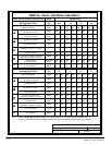
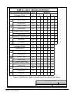
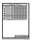
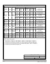
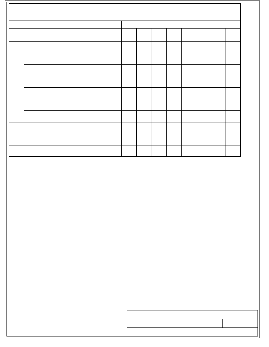
Table A- -3. Ratings & External Wiring Requirements for Powerware 9315
M B M 3 0 --- 1 6 0
kVA, 208:208VAC
Rating and External Wiring Requirement
Units Rating 60 Hz
Basic unit rating at
0.8 lagging PF load
KVA
KW
160
128
130
104
100
80
80
64
65
52
50
40
40
32
30
24
UPS Input Voltage/Bypass Input
UPS Output Voltage
VOLTS
VOLTS
208
208
208
208
208
208
208
208
208
208
208
208
208
208
208
208
A
AC Input to M aint enance Bypass
(3) Phas es , (1) Neutral, (1) Gro und
AMPS 444 361 278 222 180 139 111 83
A
Conduct o r S i ze
Number per Phase
AWG/MCM
(each)
400
(2)
400
(2)
400
(2)
300
(1)
300
(1)
300
(1)
300
(1)
300
(1)
B
AC Input to UPS Bypass
(3) Phases, (1) Ground
AMPS 444 361 278 222 180 139 111 83
B
Conduct o r S i ze
Number per Phase
AWG/MCM
(each)
400
(2)
400
(2)
400
(2)
300
(1)
300
(1)
300
(1)
300
(1)
300
(1)
C
AC Output to Critical Load
(3) Phases, (1) Neutral, (1) Ground
AMPS 444 361 278 222 180 139 111 83
C
Conduct o r S i ze
Number per Phase
AWG/MCM
(each)
400
(2)
400
(2)
400
(2)
300
(1)
300
(1)
300
(1)
300
(1)
300
(1)
D
UPS / PTC Output to M BM Cabinet (MI S )
(3) Phas es , (1 ) Neut ral, ( 1) G ro und
AMPS 444 361 278 222 180 139 111 83
D
Conduct o r S i ze
Number per Phase
AWG/MCM
(each)
400
(2)
400
(2)
400
(2)
300
(1)
300
(1)
300
(1)
300
(1)
300
(1)
E
Control Wiring to U PS
(2) Conductors
VOLTS
AMPS
120
1
120
1
120
1
120
1
120
1
120
1
120
1
120
1
Note: Callout letters A, B, C, D,and E map to drawing 164201177---6 (Reverse Transfer Connection) and
164201177---9 (Parallel Connection). Read and understand the notes on drawings when planning your installation.