


A---15
Po werware 9315 Maintenance Bypass Module 30---160kV A
164201177 Rev. C 041500
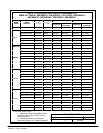
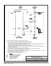
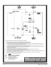
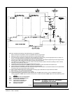
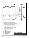
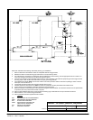
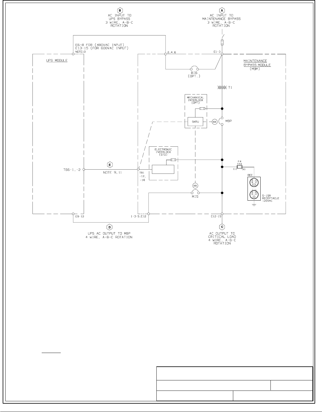
Read and understand the following notes while planning your installation:
1. Refer to national and local e lectric c odes for acceptable external wiring practices.
2. Material and labor for external wiring requirements are to be provided by others.
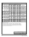
3. For external wiring requirement, including the minimum AWG size of external wiring, see the appropriate column in Table A---1.
The power wiring for this equipment is rated at 90 degrees Celsius.
4. The output of the UPS is a separately derived source. Output neutral is bonded to equipment ground through the main
bonding jumper. Refer to NEC and local codes for proper grounding practices.
5. The maintenance bypass (MBM) source must contain overcurrent protection with the maximum trip setting of 125% of the full
load input current in Table A---1.
6. The Bypass three-phase feeds should be symmetrical about ground.
7. Transfer sequen ce instructions for the MBM are placed on the breaker access panel behind the cabinet doors.
8. Control wiring must be installed in separate conduit from the power wiring.
9. Electronic interlock is a standard part of the maintenance bypass module cabinet. This electronic interlock can be replaced with
an optional (extra cost) mechanical interlock if required.
10. Refer to UPS Installation Manual for proper Bypass terminating lugs.
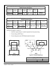
11. Refer to Table C-2 for control wiring connections.
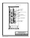
LEGEND
MIS: MAINTENANCE ISOLATION BREAKER
MBP: MAINTENANCE BYPASS BREAKER
BIB: BYPASS INPUT BREAKER
SKRU: SOLENOID KEY RELEASE UNIT
(MEC HANICAL INTERLOCK)
RT: REVERSE TRANSFER
DESCRIPTION:
DATE:
DRAWING NO:
1of1
SHEET:
REVI SI ON:
A
164201177---5
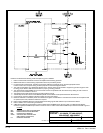
ONELINE -- 30 -160kVA, RT,
080498
110100056 D1
480:208VAC, 600:208VAC