


Installation
29
Powerware
®
9 Prestige SeriesUser’s Guide(4500/6000 VA) Rev H www.powerware.com
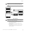
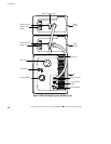
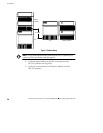
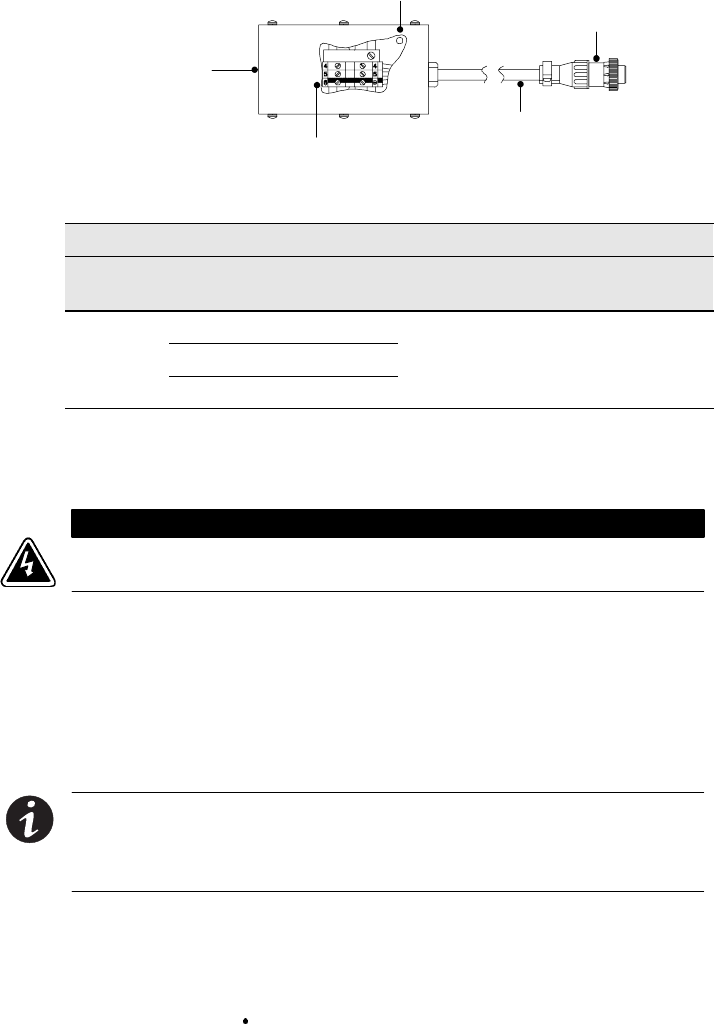
Mounting Holes
Plug/Receptacle
PPU Connector
Three Foot Cord
Terminal Block
Access Hole
for Conduit
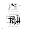
Figure 6. Optional REPO Cord Junction Box
Optional REPO Cord Junction Box Connections
Wire Function Terminal
Position
Terminal Wire Size
Rating
Suggested Wire
Size
REPO
L1 TB1-4
L2 TB1-5
12 - 22 AWG
(
4
-
0
m
m
2
)
18 AWG (0.75 mm
2
)
Ground
TB1-6
(
4
-
0
mm
2
)
(
)
N
NN
NO
OO
OT
TT
TE
EE
E The REPO function activates when L1 and L2 are shorted together.
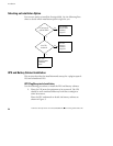
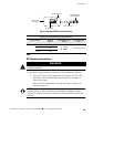
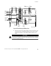
UPS Hardwired Installation
WARNING
Only qualified service personnel (such as a licensed electrician) should perform the
hardwired installation.
Use the following procedure to install the PPU and battery cabinets:
1. Place the UPS near the equipment to be protected. The UPS
should be well ventilated and away from direct sunlight or
other heat source.
Place the PPU underneath or beside the battery cabinets as
showninFigure7.
NOTE Do not connect more than six standard battery cabinets to the PPU. For
extended battery run times, contact your local distributor for additional battery
cabinets. Do not place more than six cabinets in one stack (the PPU is equal to two
cabinets).