


Installation
35
Powerware
®
9 Prestige SeriesUser’s Guide(4500/6000 VA) Rev H www.powerware.com
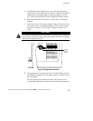
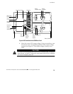
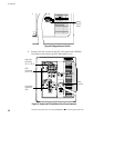
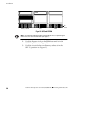
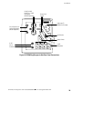
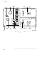
9. If you are using a REPO switch, hardwire the terminal block
TB1, positions TB1-4 through TB1-6. See the hardwired
termination table on page 33 for proper connections. Figure 10
on page 32 shows the connection locations and Figure 11 on
page 34 shows a detailed view of the terminal blocks.
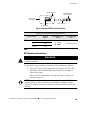
The REPO switch is a customer-supplied switch that can
disconnect the UPS output voltage from your protected
equipment. The REPO function activates when the L1 and L2
wires are shorted together. Use the following specifications for
the REPO switch:
The switch should be a wall-mounted, momentary-contact,
normally open, pushbutton switch.
Minimum ratings of 240 Vac and 35 mA.
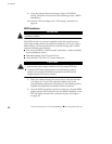
CAUTION
The Line1 and Line2 wires are at high-voltage potential (240V). Refer to your local
electrical code for proper installation of the high-voltage REPO wires.
To ensure the UPS stops supplying power to the load during any mode of
operation, the input power must be disconnected from the UPS when the
emergency power-off function is activated.
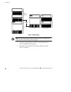
10. Replace the PPU rear panel cover.
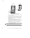
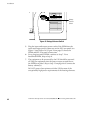
11. Plug the battery cord into the battery connector on the PPU
rear panel. All battery connectors are polarized to prevent
incorrect connection.
12. If additional battery cabinets are to be used, plug the battery
cord of the second cabinet into the battery connector of the first
cabinet after pivoting the battery connector guard out of the
way. Follow this procedure for each additional battery cabinet.
13. Remove the breaker tie from the circuit breaker on all battery
cabinets.
14. Confirm the equipment to be protected by the UPS is powered
off.
15. Start the UPS according to the following “UPS Startup”
procedure.