


Communication
66
Powerware
®
9 Prestige SeriesUser’s Guide(4500/6000 VA) Rev H www.powerware.com
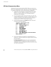
UPS Communications Interface Port
In addition to configuring the UPS for specific communication options,
you must also ensure proper use of the serial port when connecting the
UPS to your network or monitoring equipment.
NOTE Semiconductor switch contacts are rated at a maximum current of 50 mA and a
maximum of 40 Vdc.
Use only the pins specified for your communications configuration. The
use of any additional pins for any of the following interfaces can cause
interference with system communications.
Even though your network uses the specified signal lines, the pins
assigned to these signals at the network end of the cable may vary with
those of the UPS serial port. The connector body and style may vary as
well.
NOTE Standard, pin-for-pin cables may not work correctly. Consult your network
software or server manuals for system shutdown pin assignments.
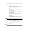
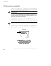
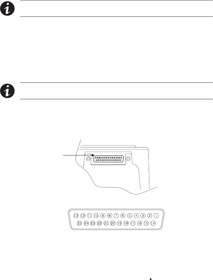
The UPS serial port complies with EIA RS-232 standards. RS-232
specifies a maximum cable length of 50 feet (15m). See Figure 27 for the
location of the serial port.
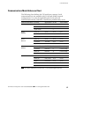
PPU Rear Panel
Serial Port Detail
Serial
Port
Figure 27. Serial Port Location