


UPS Operation
56
Powerware
®
9 Prestige SeriesUser’s Guide(4500/6000 VA) Rev H www.powerware.com
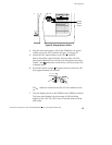
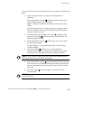
Use the following procedure to reinstall the PPU and transfer the critical
load from Maintenance Bypass (AC Line operation) to the PPU:
1. Reconnect the battery cabinet to the battery connector on the
PPU rear panel.
2. Switch the circuit breaker on all battery cabinets to the ON (
)
position.
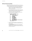
3. Confirm the correct UPS output voltage is selected according to
the PPDM model:
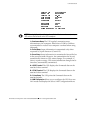
PPDM Model Number UPS Voltage Selector Switch Position*
208: 120/208 Hardwired Set to 208V for 120/208V PPDM output
Set to 220V for 127/220V PPDM output (60-Hz units only)
208: 120 L5-30R 208
208: 120/208 L6-20R 208
208: 120/208 L6-30R 208
208: 120/240 L14-30R 208
240: 120/240 Hardwired
240: 120/240 L5-30R
S
e
t
t
o
2
0
0
V
f
o
r
1
0
0
/
2
0
0
V
P
P
D
M
o
u
t
p
u
t
240: 120/240 L6-20R
S
et to 200
V
f
or 100
/
200
V
P
P
D
M
output
Set to 220V for 110
/
220V PPDM out
p
ut
240: 120/240 L6-30R
S
e
t
t
o
2
2
0
V
o
r
1
1
0
/
2
2
0
V
P
P
D
M
o
u
t
p
u
t
Set to 230V for 115/230V PPDM output
S
t
t
2
4
0
V
f
1
2
0
/
2
4
0
V
P
P
D
M
t
t
240: 120/240 L14-30R
Set to 240V for 120/240V PPDM output
240: 120/240E Hardwired
*
**
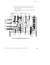
*The UPS output voltage should match local voltages.
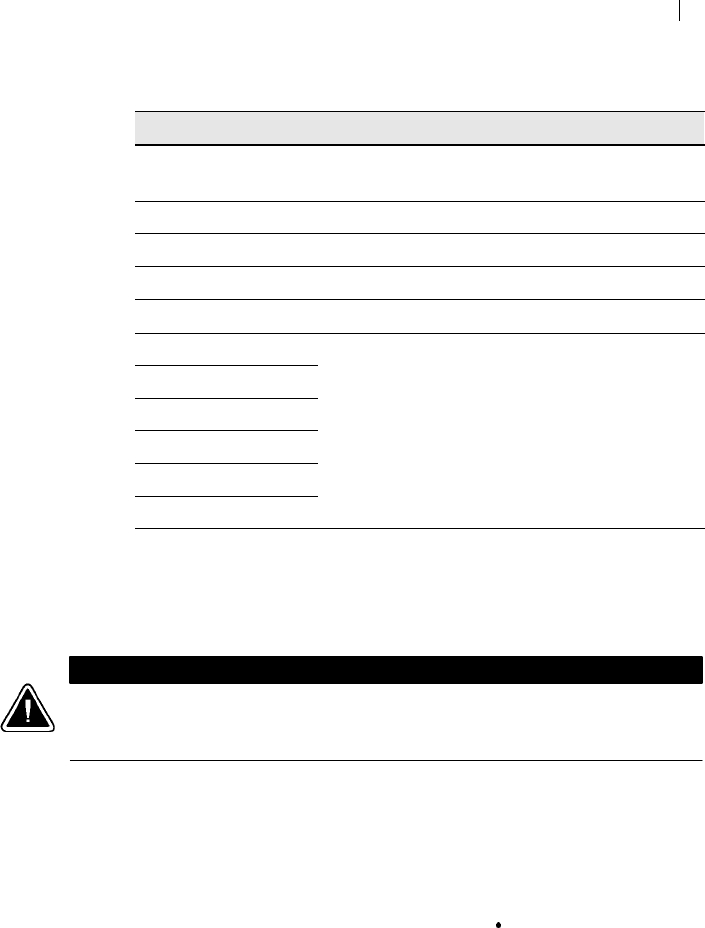
Using a screwdriver, turn the switch to the corresponding
position of the output voltage required (see Figure 25). The
output voltage is factory-set to 220V.
CAUTION
Do not turn the Voltage Selector switch while the UPS is operating (see “Changing the
Output Voltage” on page 53). Changing the output voltage while the UPS is operating
may cause an emergency power-off.