


Installation
33
Powerware
®
9 Prestige SeriesUser’s Guide(4500/6000 VA) Rev H www.powerware.com
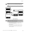
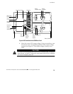
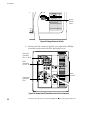
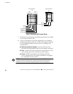
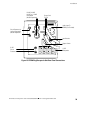
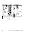
6. Hardwire the input (TB1-1 through TB1-3) and output
terminations (TB2) for the PPU. See the following hardwired
terminations table for specifications. See Figure 11 for a
detailed view of the terminal blocks.
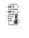
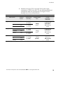
PPU Hardwired Terminations
Wire Function Terminal
Position
Terminal Wire
Size Rating
Suggested Wire
Size*
Conduit
Connection
(Entry Size)
Input
Ground TB1-1
10 - 18 AWG
(6 - 0 mm
2
)
1
0
A
W
G
11/8 (28.58 mm)
a
c
c
e
s
s
h
o
l
e
f
o
r
L1 TB1-2
8-18AWG
1
0
A
W
G
(6 mm
2
)
access
h
o
l
e
f
or
3/4
(19.05 mm)
L2/Neutral
TB1-3
8
-
1
8
A
W
G
(10 - 0 mm
2
)
(
)
/
(
)
conduit
Output
L1 TB2-1
8-18AWG
1
1
/
8
(
2
8
5
8
m
m
)
p
L2/Neutral TB2-2
8
-
1
8
A
W
G
(10 - 0 mm
2
)
10 AWG
2
1
1
/
8
(
2
8
.
5
8
mm
)
access hole for
Ground
TB2-3
10 - 18 AWG
(6 - 0 mm
2
)
(6 mm
2
)3/4(19.05 mm)
conduit
REPO
L1 TB1-4
7/8 (22.23 mm)
L2 TB1-5
12 - 22 AWG
(
4
-
0
m
m
2
)
18 AWG
(
0
7
5
m
m
2
)
/
(
)
knock-out for
1
/
2
(
1
2
7
0
m
m
)
Ground TB1-6
(
4
-
0
mm
2
)
(
0
.
7
5
mm
2
)
1
/
2
(
1
2
.
7
0
mm
)
conduit
*
**
*Use 75 C copper wire. Suggested wire size is based on Model 6000 full load ratings applied to NEC Code Table 310-16.