


Communication
67
Powerware
®
9 Prestige SeriesUser’s Guide(4500/6000 VA) Rev H www.powerware.com
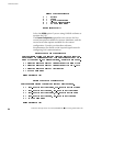
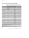
Communications Mode Reference Chart
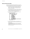
The following chart defines the UPS serial port contacts. Serial
communication is not available with 3Com and AS/400 network
configurations. Use only the applicable pins for the selected
communication mode; otherwise, interference problems may occur.
Communication Mode Function SignalName Pin No. True Condition
Serial
Data to UPS RS232 TxD 2 N/A
Data from UPS RS232 RxD 3 N/A
Signal Ground 7
Novell
(
D
f
l
)
Battery On ON.AC 14/16 Open
(Default)
Low Battery
TWO.MIN 23/24 Closed
Signal Ground 7/15/25
Novell
(
C
)
Battery On ON.AC 14/16 Closed
(Custom)
Low Battery
TWO.MIN 23/24 Closed
Signal Ground 7/15/25
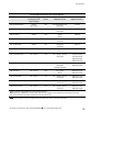
3Com
(
D
f
l
)
Shutdown (Remote) SHUT.DOWN 2 Positive Voltage
(Default)
Low Battery
LOW.BATT 9 Positive Voltage
Battery On PWR.FAIL 10 Positive Voltage
Signal Ground 7
AS/400
UPS Available UPS Available 11/13 Closed
Battery On Utility Failure 14/16 Closed
Bypass UPS Offline 17/19 Closed
Low Battery Low Battery 23/24 Closed
Signal Ground 12/15/18/25
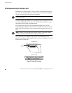
N
NN
NO
OO
OT
TT
TE
EE
E Pin numbers separated by a forward slash ( / ) are connected together internally.