


Installation
10
Powerware
®
9120 User's Guide S 05147426 A Uncontrolled Copy
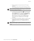
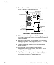
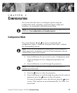
6. Remove the terminal block cover and the wiring knockouts (see
Figure 2). Retain the terminal block cover.
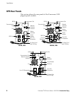
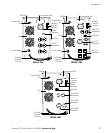
Communication Slot
USB Port
Communication Port
Fans
Network
Transient
Protector
Battery
Connector
REPO Port
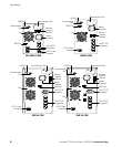
Panel Cover Screws
Panel Cover Screws
Terminal Block
Cover
Input Wiring
Access Knockout
Output Wiring
Access Knockout
Figure 2. 3000 VA, 120V Hardwired Rear Panel
7. Pull the input wires through the conduit, leaving approximately
2 ft (0.5m) of exposed wire. Attach a flexible metal fitting to the
end of the conduit.
8. Insert the conduit through the input wiring access knockout
and attach the conduit fitting to the panel. Strip 0.5I (1.5 cm)
of insulation from the end of each incoming wire.
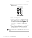
9. Connect the input and ground wires to the input terminal
block (see Figure 3).
10. Pull the output wires through the conduit, leaving
approximately 2 ft (0.5m) of exposed wire. Attach a flexible
metal fitting to the end of the conduit.
11. Insert the conduit through the output wiring access knockout
and attach the conduit fitting to the panel. Strip 0.5I (1.5 cm)
of insulation from the end of each incoming wire.