


Additional UPS Features
28
Powerware
®
9120 User's Guide S 05147426 A Uncontrolled Copy
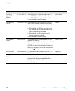
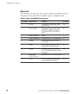
Relay Card
This interface provides true relay contact output to peripheral devices.
Outputs are user-selectable as normally open or normally closed.
Table 3. Relay Card (AS/400) Pin Assignment
Pin Number Signal Name Definition Direction
1 UPS Fail Relay contact; normally open, closes
when UPS fails.
Out
2 Summary Alarm Relay contact; normally open, closes
when UPS fails, bypass is activated,
utility power failure, or low battery
status.
Out
3 Remote Shutdown (-) Ground Ċ
4 Remote Shutdown (+) Activated by +5 to +12V for one second In
5 Common Relay common connection for pins 1, 2,
6, 7, 8, and 9.
Ċ
6 Bypass Relay contact; normally open, closes
when the UPS is in Bypass mode.
Out
7 Low Batt Low Battery relay contact; normally
open, closes when the battery is almost
discharged.
Out
8 Battery Mode
Remote Shutdown
Activated by +5 to +12V for one second. In
9 AC Fail AC Fail relay contact; normally open,
closes when utility power fails.
Out