


Additional UPS Features
22
Powerware
®
9120 User's Guide S 05147426 A Uncontrolled Copy
Use the following procedure to install the REPO switch:
1. Verify that the UPS is off and unplugged or removed from
utility power.
2. Unscrew and remove the REPO connector from the mating
plug on the UPS rear panel.
3. Remove the short wire from the REPO connector.
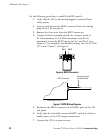
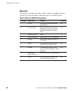
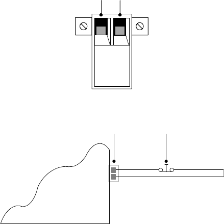
4. Connect isolated, normallyĆclosed, dry contacts (rated at
60 Vdc maximum, 30 Vac RMS maximum, and 20 mA
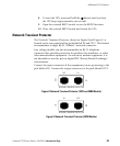
maximum) across the REPO device to Pin 1 and Pin 2 (see
Figure 6). Use stranded, nonĆshielded wiring, size 18ć22 AWG
(0.75 mm
2
ć0 mm
2
). See Figure 7.
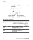
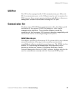
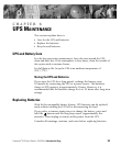
Pin 1 Pin 2Pin 1 Pin 2
Figure 6. REPO Connector
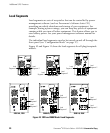
Powerware 9120 UPS
REPO Connector
Normally Closed,
Isolated Switch
Figure 7. REPO Wiring Diagram
5. Reconnect the REPO connector to the REPO port on the UPS
rear panel.
6. Verify that the externally-connected REPO switch is closed to
enable power to the UPS output connections.
7. Connect the UPS to a power source.