


Additional UPS Features
26
Powerware
®
9120 User's Guide S 05147426 A Uncontrolled Copy
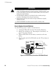
Communication Port
To establish communication between the UPS and a computer, connect
your computer to the UPS communication port using the supplied
communication cable.
When the communication cable is installed, power management
software can exchange data with the UPS. The software polls the UPS for
detailed information on the status of the power environment. If a power
emergency occurs, the software initiates the saving of all data and an
orderly shutdown of the equipment.
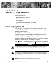
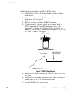
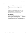
The cable pins are identified in Figure 12 and the pin functions are
described in Table 2.
3
87
9
1
6
245
Figure 12. Communication Port
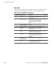
Table 2. Communication Port Pin Assignment
Pin
Number
Signal Name Function Direction from
the Multi-Port
Module
1 Low Batt Low Battery relay contact Out
2 RxD Transmit to external device Out
3
TxD Receive from external device In
RS-232 low
level signal for
>0.4 seconds
Conditional Power Off: In absence of AC
power, output is turned off until normal AC
power returns
In
4 Ċ No Connection Ċ
5 GND Signal Ground Ċ
6 Ċ No Connection Ċ
7 Ċ No Connection Ċ
8 AC Fail AC Fail relay contact Out
9 Power Source +V (8 to 24 volts DC power) Out