


Additional UPS Features
23
Powerware
®
9120 User's Guide S 05147426 A Uncontrolled Copy
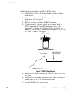
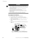
8. To start the UPS, press and hold the button until you hear
the UPS beep (approximately one second).
9. Open the external REPO switch to test the REPO function.
10. Close the external REPO switch and restart the UPS.
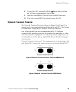
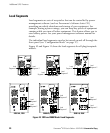
Network Transient Protector
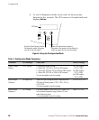
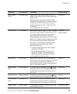
The Network Transient Protector, shown in Figure 8 and Figure 9, is
located on the rear panel and has jacks labeled IN and OUT. This feature
accommodates a single RJĆ45 (10BaseT) network connector.
Low voltage models can also accommodate an RJĆ11 telephone
connector that provides protection for modems, fax machines, or other
telecommunications equipment. As with most modem equipment, it is
not advisable to use this jack in digital PBX (Private Branch Exchange)
environments.
Connect the input connector of the equipment you are protecting to the
jack labeled IN. Connect the output connector to the jack labeled OUT.
OUT
IN
IN
OUT
NETWORK TRANSIENT PROTECTOR
Figure 8. Network Transient Protector (120V and 208V Models)
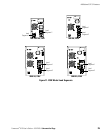
IN
OUT
OUT
IN
NETWORK TRANSIENT PROTECTOR
Figure 9. Network Transient Protector (230V Models)