


Installation
19
Powerware
®
9125 Two-in-One (5000/6000 VA) PDM User’s Guide S Rev B www.powerware.com
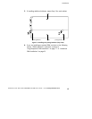
5. If an emergency power-off (disconnect) switch is required by
local codes, see “Remote Emergency Power-Off” on page 21 to
install the REPO switch before powering on the UPS.
6. Neutral-to-Ground Bonding. The PDM has a neutral-to-ground
(N-G or neutral -to-earth) bonding screw as required under
safety regulations issued by various regulatory agencies. If the
neutral-to-ground connection is not needed, remove the screw
to remove the bond between neutral and ground.
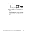
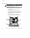
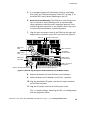
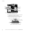
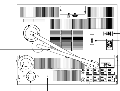
7. Plug the input and output cords of the PDM into the input and
output power connectors on the UPS rear panel (see Figure 8).
PDM Input
Cord
PDM Output
Cord
PDM Input
Connector
PDM L6-30 Output Receptacle
PDM 5-15 Output
Receptacles
PDM Output
Circuit Breaker
REPO Connector
Communication PortUSB Port
UPS Battery
Circuit Breaker
Neutral-to-Ground Bonding Screw
Figure 8. UPS and Plug-Receptacle PDM Installation (L6-30 Model shown)
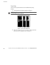
8. Remove the breaker tie from all battery circuit breakers.
9. Switch all battery circuit breakers to the ON ( | ) position.
10. Plug the detachable UPS power cord into the input connector
on the PDM rear panel.
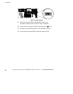
11. Plug the UPS power cord into an L6-30 power outlet.
The
µ
indicator flashes, indicating the UPS is in Standby mode
with the equipment offline.