


Installation
25
Powerware
®
9125 Two-in-One (5000/6000 VA) PDM User’s Guide S Rev B www.powerware.com
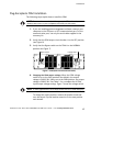
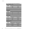
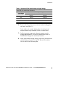
Table 2. Hardwired PDM Input/Output Voltage Settings
PPDM HW, and PPDM EURO HW Models
I
n
p
u
t
V
o
l
t
a
g
e
PDM Output Voltage
Input Voltage
(from UPS)
208V Switch Po sition
(HV/LV)
Default 240V Switch Position
(HV/LV)
208 208/120 208/104
220 220/126 220/110
230 230/131 230/115
240 240/136 240/120
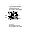
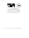
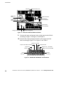
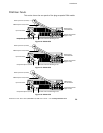
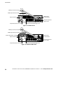
6. Remove the wiring access cover and the conduit landing p late
and retain (see Figure 11).
Punch holes in the conduit landing plate for the input and
output conduit using a Greenlee
®
punch or similar device.
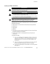
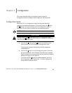
7. Pull the input and output wires through separate conduit,
leaving approximately 2 ft (0.5m) of exposed wire. Attach a
flexible metal fitting to the end of each conduit.
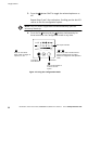
8. Insert each conduit through a wiring access entry and attach the
conduit fitting to the panel. Strip 0.35I (9 mm) of insulation
from the end of each incoming wire.