


Installation
21
Powerware
®
9125 Two-in-One (5000/6000 VA) PDM User’s Guide S Rev B www.powerware.com
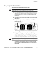
Remote Emergency Power-Off
The Powerware 9125 includes a REPO connector that allows power to be
switched off at the UPS output receptacles from a customer-supplied
switch in a remote location.
The REPO feature shuts down the protected equipment immediately,
whether or not the UPS is in Nor mal or Battery mode, and does not
follow the orderly shutdown procedure initiated by any power
management software. The UPS switches to Standby mode.
When the REPO switch is reset, the equipment will not return to battery
power until the UPS is manually restarted.
If the Off
button is pressed after the REPO is activated, the UPS
remains in Standby mode when restarted until the On
button is
pressed.
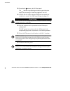
WARNING
The R EPO circuit is an IEC 60950 safety extra low voltage ( SELV) circuit. This
circuit must be separated from any hazardous voltage circuits by reinforced
insulation.
CAUTION
To ensure the UPS stops supplying power to the load during any mode of
operation, th e input power must be disconnected from the UPS when the
emergency p ower-off function is activated.
NOTE The REPO function activates when the REPO contacts close.
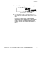
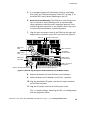
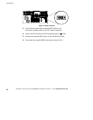
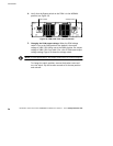
Use the following procedure to install the REPO switch:
1. Verify that the UPS is off and unplugged.
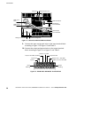
2. Connect the switch or circuit to the REPO connector on the UPS
rear panel using insulated 18–20 AWG (0.75 mm
2
–0.5 mm
2
)
wire. See Figure 9.
NOTE A separate contact must simultaneously cause UPS input AC
power to be removed.