


Installation
27
Powerware
®
9125 Two-in-One (5000/6000 VA) PDM User’s Guide S Rev B www.powerware.com
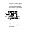
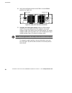
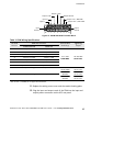
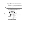
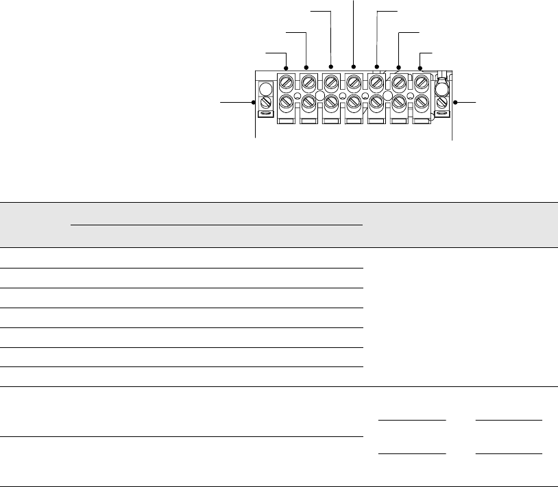
Output Line 2, 208
–240V
Output Neutral
Output
Ground
Input L1
Input L2
Input
Ground
Output +120V
Output -120V
Output Line 1, 208–240V
E4 1 2 3 4 5 6 7 E5
Figure 13. PPDM HW Model Terminal Block
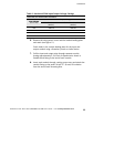
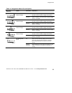
Table 3. PDM Wiring Specifications
Terminal
PDM Wire Function
Terminal Wire Ti
g
htenin
g
T
e
r
m
i
n
a
l
Position
PPDM EURO HW PPDM HW
T
e
r
m
i
n
a
l
W
i
r
e
Size Rating*
T
i
g
h
t
e
n
i
n
g
Torque
1 InputLine1 InputLine1
2 InputLine2/N InputLine2
3 Output 230–240V (Isolated) Output -120V
2
4 Output 115–120V Output +120V
2–17 mm
2
(
1
4
–
6
A
W
G
)
1.8 ±0.22 Nm
(
1
6
±
2
i
n
l
b
)
5 Output Neutral Output Neutral
(
1
4
–
6
A
W
G
)
(
1
6
±
2
i
n
l
b
)
6 Output Line 1, 230–240V Output Line 1, 208–240V
7 Output Line 2/N, 230–240V Output Line 2, 208–240V
E4 Input Earthing Input Ground
2–5 mm
2
(14–10 AWG)
8mm
2
2.26 ±0.22 Nm
(20 ±2inlb)
2.82 ±0.22 Nm
E5 Output Earthing Output Ground
8
m
m
(8 AWG)
17 mm
2
(6 AWG)
2
.
8
2
±
0
.
2
2
N
m
(25 ±2inlb)
3.95 ±0.22 Nm
(35 ±2inlb)
*Use 2.0 mm
2
(14 AWG) 75_C copper wire minimum.
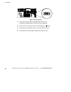
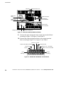
11. Replace the wiring access cover and the conduit landing plate.
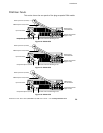
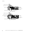
12. Plug the input and output cords of the PDM into the input and
output power connectors on the UPS rear panel.