


Operation
36
Powerware
®
9125 Two-in-One (5000/6000 VA) PDM User’s Guide S Rev B www.powerware.com
Use the following procedure to reinstall the UPS and transfer your
equipment from Maintenance Bypass (AC Line operation) to the UPS:
1. If optional EBM(s) are installed, reconnect the EBM cable to the
battery connector on the UPS rear panel.
Switch the battery circuit breaker on the first EBM rear panel to
the ON ( | ) position.
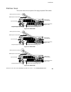
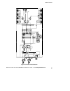
2. Plug the input and output cords of the PDM into the input and
output power connectors on the UPS rear panel (see Figure 8
on page 19).
The
µ
indicator flashes, indicating the UPS is in Standby mode
with the equipment offline.
3. Press the On button on the UPS front panel.
The
µ
indicator stops flashing.
4. If the PDM voltage switch is set to 208V, confirm the UPS output
voltage through the front panel (see page 31).
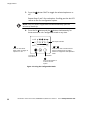
5. Turn the Bypass switch on the PDM to the NORMAL position.
The bar graph indicators display the percentage of load being
applied to the UPS. The UPS is now in Normal mode and
supplying power to your equipment.
6. Reinstall the PDM front panel.