


1of4
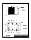
INTERFACE AND CONTROL WIRING
INSTALLATION NOTES AND
TERMINAL LOCATIONS
063006D
DESCRIPTION:
DATE:
DRAWING NO: SHEET:
REVISION:
164201546---7
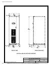
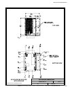
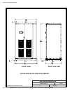
INSTALLATION INFORMATION
EATON Powerware
®
9390 UPS Sidecar Installation and Operation Manual S 164201586 Rev E www.powerware.com
A-64
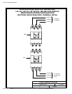
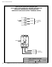
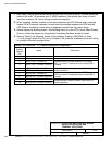
1. Use Class 1 wiring methods (as defined by the NEC) for control wiring. The wire should be
rated at 600 volts, 1A minimum and 12 AWG maximum. Use twisted–pair wires for each
input and common. All control wiring is customer-supplied.
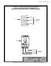
2. When installing auxiliary contact control w iring between the UPS Sidecar and a remotely
located UPM 2 interface terminals, conduit must be installed between the UPM and the
UPS Sidecar. Install the control w iring in separate conduit from the power wiring.
3. Alarms display as Building Alarm 1 and B uilding Alarm 2 on the UPS Control Panel Display
Screen, unless the alarms are programmed to display the alarm functional name.
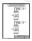
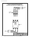
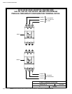
4. Refer to Table R, the following sheets of this drawing, Drawing 164201546---6, sheet
11 of 34 through sheet 20 of 34, and to Chapter 2 for customer interface and control wiring
for parallel redundant configurations.
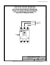
Table R. TB1 Terminals – 1+1 Parallel Redundant Configuration
UPS
Sidecar
Terminal
TB1
Name Description
1 Not Used
2 Not Used
3 MOB 1 Aux 1 Contact NC
Contacts used to indicate whether UPS Sidecar
MOB 1 is closed. Contacts are open when MOB 1
is closed.
4 MOB 1 Aux 1 Contact Common
5 MOB 1 Aux 2 Contact NO
Contacts used for backup control (pull chain) for
parallel operation.
6 MOB 1 Aux 2 Contact Common
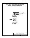
7 MOB 2 Aux 1 Contact NC
Contacts used to indicate whether UPS Sidecar
MOB 2 is closed. Contacts are open when MOB 2
is closed.
8 MOB 2 Aux 1 Contact Common
9 MOB 2 Aux 2 Contact NO
Contacts used for backup control (pull chain) for
parallel operation.
10 MOB 2 Aux 2 Contact Common