


1of10
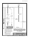
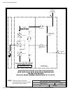
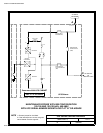
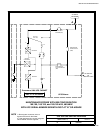
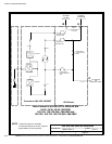
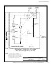
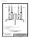
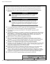
POWER WIRING INSTALLATION NOTES
092107
DESCRIPTION:
DATE:
DRAWING NO: SHEET:
REVISION:
D
164201546---4
INSTALLATION INFORMATION
EATON Powerware
®
9390 UPS Sidecar Installation and Operation Manual S 164201586 Rev E www.powerware.com
A-17
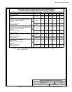
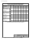
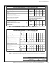
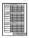
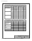
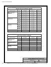
Table B. INPUT/OUTPUT Ratings & External Wiring Requirements for
Powerware 9390 UPS Sidecar (Maintenance Bypass) 208/208V
Units Rating 50/60 Hz
Basic Unit Rating
UPS kVA 20 30 40 50 60 80
Input and Bypass Input
Output
VOLTS
VOLTS
208
208
208
208
208
208
208
208
208
208
208
208
AC Input to Maintenance Bypass (without
BIB or RIB, or dual feed with BIB and RIB)
(3) Phases, (1 ) Neutr al---if required,
(1) Ground
A
AMPS 56 83 111 139 167 222
Minimum Conductor Size
Number per Phase
AWG or kcmil
(each)
2
(1)
2/0
(1)
2/0
(1)
4/0
(1)
250
(1)
2/0
(2)
AC Input to Maintenance Bypass (single
feed with BIB, or single feed with BIB and RIB)
(3) Phases, (1 ) Neutr al---if required,
(1) Ground
A
AMPS 60 90 125 155 185 240
Minimum Conductor Size
Number per Phase
AWG or kcmil
(each)
2
(1)
2/0
(1)
2/0
(1)
4/0
(1)
250
(1)
2/0
(2)
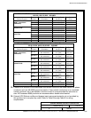
AC Input to Optional RIB
(3) Phases, (1) Ground
B
AMPS 60 90 125 155 185 240
Minimum Conductor Size
Number per Phase
AWG or kcmil
(each)
2
(1)
2/0
(1)
2/0
(1)
4/0
(1)
250
(1)
2/0
(2)
AC Output to Critical Load
F ull Load Current
(3) Phases, (1) Neutral---if required,
(1) G round
C
AMPS 56 83 111 139 167 222
Minimum Conductor Size
Number p er Phase
AWG or kcmil
(each)
2
(1)
2/0
(1)
2/0
(1)
4/0
(1)
250
(1)
2/0
(2)
NOTE Callout letters A, B, and C map to drawing 164201546---3, sheets 1 of 11,
5 o f 11, and 9 of 11.