


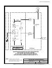
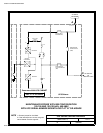
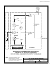
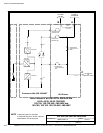
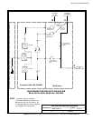
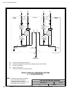

POWER WIRING INSTALLATION NOTES
092107
DESCRIPTION:
DATE:
DRAWING NO: SHEET:
REVISION:
D
164201546---4 3 of 10
INSTALLATION INFORMATION
EATON Powerware
®
9390 UPS Sidecar Installation and Operation Manual S 164201586 Rev E www.powerware.com
A-19
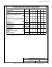
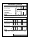
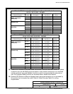
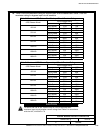
Table D. INPUT/OUTPUT Ratings & External Wiring Requirements for
Powerware 9390 UPS Sidecar (1+1 Parallel Redundant) 208V
Units Rating 50/60 Hz
Basic Unit Rating
UPS kVA
40 50 60 80
Input and Bypass Input
Output
VOLTS
VOLTS
208
208
208
208
208
208
208
208
AC Input from UPM
F ull Load Current for each Module
(3) Phas es , (1) Neutral---if required, (1) Gro und
—
AMPS
111 139 167 222
Minimum Conductor Size for each Module
NumberperPhaseforeachModule
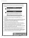
For c ustomer-supplied wiring in a standalone
installation, refer to the applicable Powerware 9390
installation and operation manual, listed in paragraph
1.5, for wire size. Wiring for line-up-and-match
installation is factory-supplied.
AC Output to Critical Load
F ull Load Current
(3) Phas es , (1) Neutral---if required, (1) Ground
D
AMPS
111 139 167 222
Minimum Conductor Size
Number p er Phase
AWG or kcmil
(each)
2/0
(1)
4/0
(1)
250
(1)
2/0
(2)
NOTE Callout letter D maps to drawing 164201546---3, sheet 11 of 11.
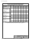
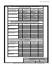
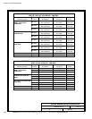
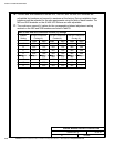
Table E. INPUT/OUTPUT Ratings & External Wiring Requirements for
Powerware 9390 UPS Sidecar (1+1 Parallel Redundant) 480V
Units Rating 50/60 Hz
Basic Unit Rating
UPS
kVA
20
(See
Note 2)
30
(See
Note 2)
40 50 60 80 100 120 160
Input and Bypass Input
Output
VOLTS
VOLTS
480
480
480
480
480
480
480
480
480
480
480
480
480
480
480
480
480
480
AC Input from UPM
F ull Load Current for each Module
(3) Phases, (1) Neutral---if required,
(1) Gr ound
—
AMPS
48 48 48 60 72 96 120 144 192
Minimum Conductor Size for each
Module
NumberperPhaseforeachModule
For c ustomer-supplied wiring in a standalone installation, refer to the applicable
Powerware 9390 installation and operation manual, listed in paragraph 1.5, for wire
size. Wiring for lin e-up -and -ma tch installation is factory-supplied.
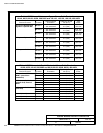
AC Output to Critical Load
F ull Load Current
(3) Phases, (1) Neutral---if required,
(1) Gr ound
D
AMPS
48 48 48 60 72 96 120 144 192
Minimum Conductor Size
Number p er Phase
AWG or
kcmil
(each)
4
(1)
4
(1)
4
(1)
2
(1)
1
(1)
1/0
(1)
4/0
(1)
4/0
(1)
1/0
(2)
NOTE 1. Callout letter D maps to drawing 1 64201546---3, sheet 11 of 11.
NOTE 2. 40/20 kVA and 40/30 kV A parallel systems must be wired same as a 40/40 kVA.