


UPS SIDECAR FEATURES, CONTROLS, AND OPERATION
EATON Powerware
®
9390 UPS Sidecar Installation and Operation Manual S 164201586 Rev E www.powerware.com
4-15
4.6 UPS Sidecar Operation – Parallel Redundant Configuration
1. Remove the screw securing the bottom of the UPS Sidecar front panel. Lift up
the panel and remove.
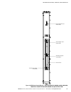
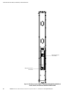
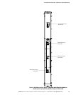
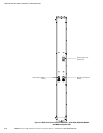
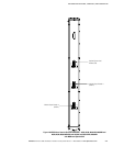
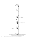
2. Verify that the UPS Sidecar circuit breakers are set as follows:
Module Output Breaker 1 (MOB 1) CLOSED
Module Output Breaker 2 (MOB 2) CLOSED
System Load Breaker (SLB) (if installed) CLOSED
3. Reinstall the UPS Sidecar front panel and secure with the screw at the bottom of
the panel.
4. Start the UPS in Normal mode according to the Multiple Module Parallel
Operation instructions in the operation chapter of the applicable Powerware 9390
installation and operation manual, listed in paragraph 1.5.
4.7 Maintaining the UPS Sidecar
The UPS Sidecar maintenance is the same as the UPS. Refer to the applicable
Powerware 9390 installation and operation manual, listed in paragraph 1.5, for
maintenance instructions.
4.8 Product Specifications
The UPS Sidecar specifications are the same as the UPS. Refer to the applicable
Powerware 9390 installation and operation manual, listed in paragraph 1.5, for product
specifications.