


EATON Powerware
®
9390 UPS Sidecar Installation and Operation Manual S 164201586 Rev E www.powerware.com
2-1
Chapter 2 Installing the UPS Sidecar
2.1 Installation Plan and Unpacking
Refer to the applicable Powerware 9390 installation and operation manual, listed in
paragraph 1.5, for installation planning and unpacking.
2.2 Preliminary Installation Information
WARNING
Installation should be performed only by qualified personnel.
Refer to the following while installing the UPS Sidecar:
S Appendix A contains installation drawings and additional installation notes.
S Dimensions are in millimeters and inches.
S The conduit landing plates are to be removed to add conduit landing holes, or
remove knockouts, as required. Plate material is 16 gauge steel (1.5 mm/0.060”
thick).
S Refer to the applicable Powerware 9390 installation and operation manual, listed in
paragraph 1.5, for UPS cabinet installation, wiring information, and conduit and
terminal locations.
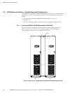
2.3 UPS Sidecar Installation – Maintenance Bypass Configuration
2.3.1 Installing the UPS Cabinet with UPS Sidecar
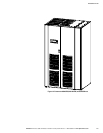
The UPS Sidecar is a factory-installed integral part of the standard UPS cabinet. Refer
to the applicable Powerware 9390 installation and operation manual, listed in
paragraph 1.5, for UPS cabinet installation.
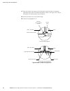
2.3.2 Installing Maintenance Bypass Power Wiring
NOTE Remove the UPS Sidecar top or bottom conduit landing plate to drill or punch conduit holes, or
remove knockouts (see Drawing 164201546-5 starting on page A-27).
NOTE Refer to the applicable Powerware 9390 installation and operation manual, listed in paragraph 1.5,
for UPS cabinet wiring information and conduit and terminal locations.
NOTE If input or output neutrals are required, wire the neutrals to the neutral terminals located inside the
UPS cabinet.
NOTE Wire grounds to the ground terminals located inside the UPS cabinet.
1. Verify the UPS system is turned off and all power sources are removed. Refer to
the applicable Powerware 9390 installation and operation manual, listed in
paragraph 1.5, for shutdown instructions.
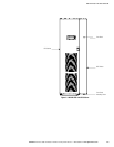
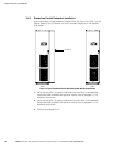
2. If not already removed, remove the screw securing the bottom of the UPS
Sidecar front panel (see Figure 2-1). Lift up the panel and remove.
Figure