


INSTALLING THE UPS SIDECAR
EATON Powerware
®
9390 UPS Sidecar Installation and Operation Manual S 164201586 Rev E www.powerware.com
2-9
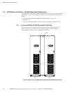
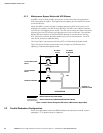
2.4.4 Installing Standalone Parallel Redundant Power Wiring
NOTE Remove the UPS Sidecar top or bottom conduit landing plate to drill or punch conduit holes, or
remove knockouts (see Drawing 164201546-5 starting on page A-27).
NOTE Refer to the applicable Powerware 9390 installation and operation manual, listed in paragraph 1.5,
for UPS cabinet wiring information and conduit and terminal locations.
CAUTION
Specified wiring and the MOB and SLB breakers for the UPS Sidecar are rated for parallel redundant service
only. DO NOT use as a parallel capacity system.
CAUTION
Parallel system wiring length should be in accordance with the parallel drawings found in the appendix of
the applicable Powerware 9390 installation and operation manual, listed in paragraph 1.5. Correct wire
length ensures approximate equal current sharing when in Static Bypass mode.
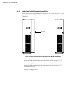
1. Verify the UPS system is turned off and all power sources are removed. Refer to
the applicable Powerware 9390 installation and operation manual, listed in
paragraph 1.5, for shutdown instructions.
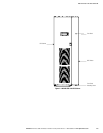
2. If not already removed, remove the screw securing the bottom of the UPS
Sidecar front panel (see Figure 2-1 on page 2-3). Lift up the panel and remove.
3. If not already removed, remove the screws securing the internal safety shield
panel and remove the panel to gain access to the terminals.
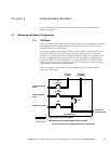
4. Route and connect output cables from UPM 2 to MOB 2 in the UPM 1 UPS
Sidecar. See Drawing 164201546-6, starting on page A-30, for UPS Sidecar
wiring access information and terminal locations.
5. Connect phase A, B, and C, and Neutral power wiring from UPM 2 to MOB 2.
6. Route the output cables to the UPS Sidecar output terminals. See Drawing
164201546-6, starting on page A-30, for UPS Sidecar wiring access information
and terminal locations.
7. Connect phase A, B, and C, and Neutral power wiring from the UPS Sidecar
output terminals to the critical load.
8. After wiring the UPS system to the facility power and critical load, be sure to
ground the system according t o local and/or national electrical wiring codes.
9. If wiring interface connections, proceed to paragraph 2.4.5; otherwise, proceed
to Step 10.
10. When all wiring is complete, reinstall the internal safety shield panels removed in
previous steps.
11. Reinstall the UPS Sidecar front panel and secure with the screw at the bottom of
the panel.