


UPS SIDECAR FEATURES, CONTROLS, AND OPERATION
EATON Powerware
®
9390 UPS Sidecar Installation and Operation Manual S 164201586 Rev E www.powerware.com
4-3
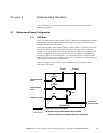
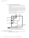
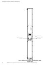
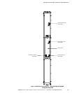
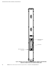
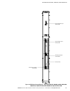
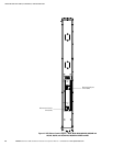
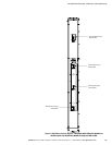
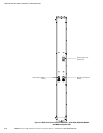
4.4 UPS Sidecar Controls
Figure 4-1 through Figure 4-8 identify and show the location of the controls on the
Powerware 9390 UPS Sidecar.
NOTE Read the operation sections of this manual and the applicable Powerware 9390 installation and
operation manual, listed in paragraph 1.5, and have thorough knowledge of UPS operation before attempting
to operate any of the UPS Sidecar controls.
The UPS Sidecar can contain the following controls:
Maintenance Bypass Configuration
S Maintenance Bypass Switch (Standard)
S Maintenance Isolation Switch (Standard)
S Bypass Input Breaker (Optional)
S Rectifier Input Breaker (Optional)
Parallel Redundant Configuration
S Module Output Breaker 1 (Standard)
S Module Output Breaker 2 (Standard)
S System Load Breaker (Optional)