


INSTALLING THE UPS SIDECAR
EATON Powerware
®
9390 UPS Sidecar Installation and Operation Manual S 164201586 Rev E www.powerware.com
2-5
1. Verify that the UPM 1 is properly installed and secured. Refer to the applicable
Powerware 9390 installation and operation manual, listed in paragraph 1.5, for
installation instructions.
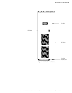
2. On UPM 1, if not already removed, remove the screw securing the bottom of the
UPS Sidecar front panel (see Figure 2-1 on page 2-3). Lift up the panel and
remove.
3. On UPM 1, if not already removed, remove the screws securing the internal
safety shield panel and remove the panel to gain access to the terminals.
4. Remove the field kit from the bottom of the UPS Sidecar and retain for later use.
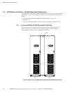
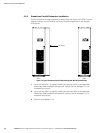
5. Roll UPM 2 to an area near the right-hand side of UPM 1.
6. Open or remove doors, internal safety shield panels, and cosmetic covers, as
required, according to the instructions contained in the applicable Powerware
9390 installation and operation manual, listed in paragraph 1.5.
7. Remove the knockouts, as required, on the bottom right side inside panel of the
UPM 1 UPS Sidecar (see Drawing 164201546-5, sheet 3 of 3, on page A-29).
8. Remove the knockouts on the bottom left side inside panel of UPM 2. Refer to
the applicable Powerware 9390 installation and operation manual, listed in
paragraph 1.5, for the location of the knockout plug.
9. Install the nylon grommets from the field kit around the holes left after removing
the knockouts.
10. Push UPM 2 toward the right side of UPM 1 until the doors are flush with each
other.
11. If not already installed, mount the hanger brackets to the top right side of the
UPM 2 using M4 screws (see Drawing 164201546-5, sheet 3 of 3, on
page A-29).
12. If not already installed, hang the side panel on the hanger brackets and align with
the front and rear of the UPM 2.
13. Secure UPM 2 in position. Refer to the applicable Powerware 9390 installation
and operation manual, listed in paragraph 1.5, for installation instructions.
NOTE Two cabinet joining brackets are provided in the field kit for securing each cabinet at the top and
bottom. A small flat bracket joins the top of the cabinets and a larger angle bracket joins the cabinets at the
bottom. The small flat bracket is attached to the cabinet tops first.
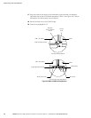
14. Remove the left-hand screw from the top door hinge on UPM 2.
15. Locate the small flat bracket, four washers, and M 4 screw from the field kit.
Align the holes in the small flat bracket over t he hole in the top of the UPS
Sidecar attached to UPM 1 and the door hinge screw hole on UPM 2. Use the
four washers between the bracket and the top of the UPS Sidecar to match the
thickness of hinge on UPM 2. Secure the bracket to the UPS Sidecar using the
M4 screw, and to the hinge on UPM 2 using the screw removed in Step 14 (see
Figure 2-3).
16. Locate the large angle b racket, M4 screws, and large nut from the field kit. Place
one end of the bracket over the bolt on the bottom side of t he lower left-hand
hinge on UPM 2, and loosely secure the bracket to the hinge with the large nut
(see Figure 2-3).