68
Chapter 3 ANSI EVFU
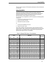
Each “channel control code” pair of bytes has the capability to indicate
multiple channels since each channel indication has a unique bit position
which is either ON - 1 or OFF - 0.
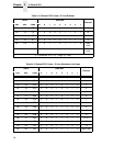
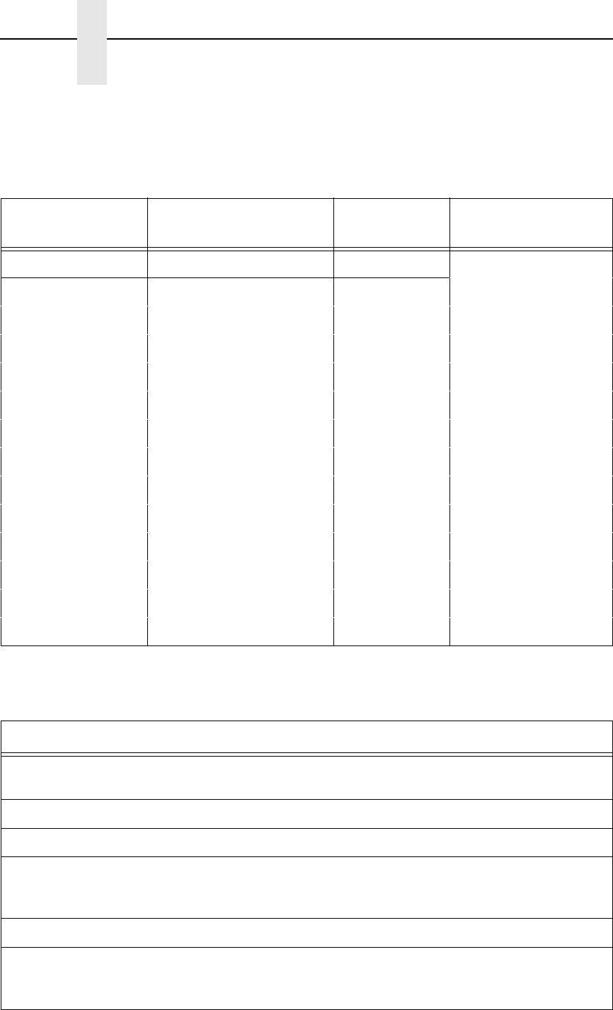
Table 24 is a sample program to load an EVFU table.
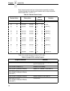
Table 23. Channel Control Codes
Decimal Value Binary Value
ASCII
Character
Remarks
12 1 212
64 64 1000000 1000000 @ @ Fillers
65 64 1000001 1000000 A @ Channel 1
66 64 1000010 1000000 B @ Channel 2
68 64 1000100 1000000 D @ Channel 3
72 64 1001000 1000000 H @ Channel 4
80 64 1010000 1000000 P @ Channel 5
96 64 1100000 1000000 ‘ @ Channel 6
64 65 1000000 1000001 @ A Channel 7
64 66 1000000 1000010 @ B Channel 8
64 68 1000000 1000100 @ D Channel 9
64 72 1000000 1001000 @ H Channel 10
64 80 1000000 1010000 @ P Channel 11
64 96 1000000 1100000 @ ‘ Channel 12
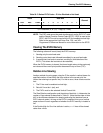
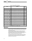
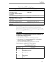
Table 24. Sample EVFU Loading Program
Program Instruction Remarks
1500 WIDTH “LPT1:”,255 Required by some BASIC languages to avoid
auto LF at column 80
1510 LPRINT CHR$(27);“]!”; Enables EVFU loading.
1520 LPRINT CHR$(65);CHR$(64); Resets TOF, Channel 1. See Table 23.
1530 FOR I=1 TO 4
1531 LPRINT CHR$(64);CHR$(64);
1532 NEXT I
4 filler lines
1540 LPRINT CHR$(68);CHR$(64); Selects Channel 3. See Table 23.
1550 FOR I=1 TO 18
1551 LPRINT CHR$(64);CHR$(64);
1552 NEXT I
18 filler lines


