


2 – General Description
Chassis Controls and LEDs
59021-04 C 2-3
Q
2.1.3
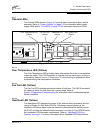
Chassis LEDs
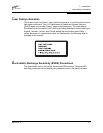
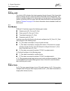
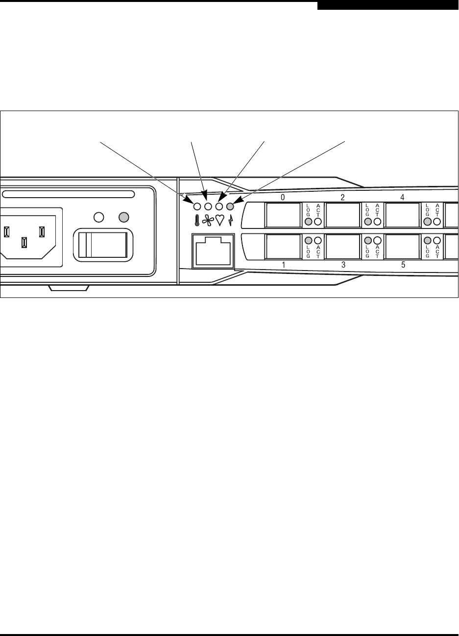
The chassis LEDs shown in Figure 2-3 provide status information about switch
operation. Refer to ”Power Supplies” on page 2-9 for information about power
supply LEDs and to ”Port LEDs” on page 2-5 for information about port LEDs.
Figure 2-3. Chassis LEDs
2.1.3.1
Over Temperature LED (Yellow)
The Over Temperature LED provides status information about the air temperature
inside the switch. This LED illuminates to indicate that the switch logic circuitry is
overheating. Refer to Section 5 Diagnostics/Troubleshooting for information about
troubleshooting over temperature conditions.
2.1.3.2
Fan Fail LED (Yellow)
The Fan Fail LED indicates operational status of both fans. This LED illuminates if
the speed of either fan falls below the normal range. Refer to
Section 5 Diagnostics/Troubleshooting for information about troubleshooting fan
failure conditions.
2.1.3.3
Heartbeat LED (Yellow)
The Heartbeat LED indicates the status of the internal switch processor and the
results of Power On Self Tests (POSTs). Following a normal power-up, the
Heartbeat LED blinks about once per second to indicate that the switch passed
the POST and that the internal switch processor is running. In force PROM mode,
the Heartbeat LED illuminates continuously. Refer to ”Heartbeat LED Blink
Patterns” on page 5-1 for more information about Heartbeat LED blink patterns.
Over Temperature LED
(Yellow)
Input Power LED
(Green)
Fan Fail LED
(Yellow)
Heartbeat LED
(Yellow)