


2 – General Description
Power Supplies
59021-04 C 2-9
Q
2.5
Power Supplies
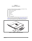
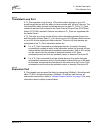
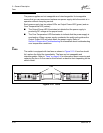
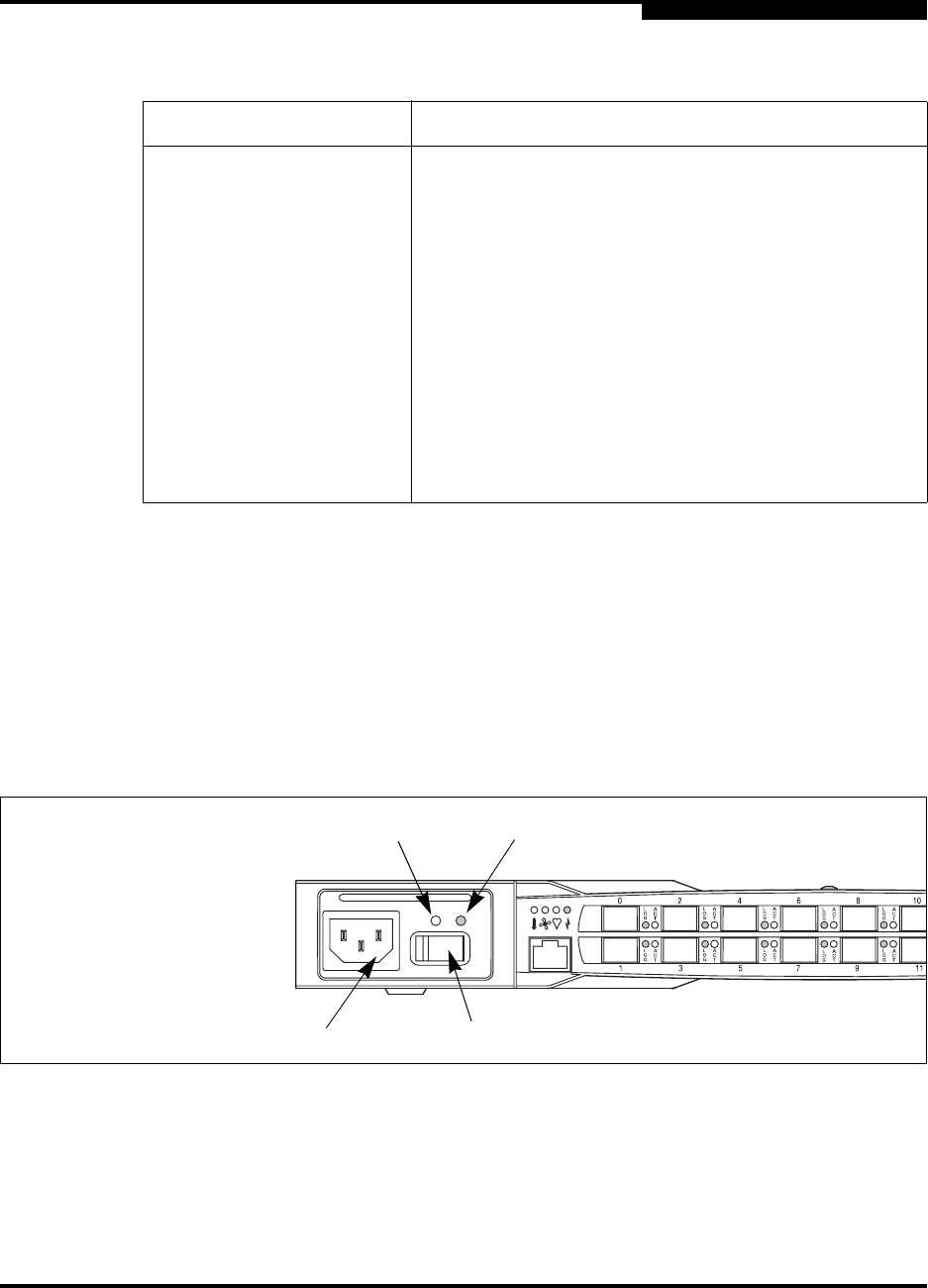
The power supplies convert standard 110 or 230 VAC to DC voltages for the
various switch circuits. Each power supply has an AC power receptacle, an On/Off
switch, and two status LEDs as shown in Figure 2-9. After connecting a power
supply to an AC voltage source and placing the power switch in the On position,
the power supply is energized and DC voltage is delivered to the switch logic
circuitry. Refer to Section 6 Removal/Replacement for information about replacing
a power supply.
Figure 2-9. Power Supply Components
Each power supply is capable of providing all of the switch’s power needs. During
normal operation, each power supply provides half of the demand. If one power
supply goes offline, the second power supply steps up and provides the
difference.
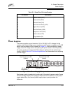
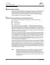
Table 2-1. Serial Port Pin Identification
Pin Number Description
1 Carrier Detect (DCD)
2 Receive Data (RxD)
3 Transmit Data (TxD)
4 Data Terminal Ready (DTR)
5 Signal Ground (GND)
6 Data Set Ready (DSR)
7 Request to Send (RTS)
8 Clear to Send (CTS)
9 Ring Indicator (RI)
AC Power
Receptacle
Output Power LED
(Green)
Over Temperature LED
(Amber)
On/Off Switch