


iv PARAGON II USER MANUAL
Figure 47 Stacking - Single Base Configuration with P2-UMT832M and P2-UMT832S................55
Figure 48 Stacking - Single Base Configuration with P2-UMT832M and P2-UMT832S................55
Figure 49 Stacking - Single Base Configuration with P2-UMT832M and P2-UMT832S................56
Figure 50 Stacking - Single Base Configuration with P2-UMT1664M and P2-UMT832S..............56
Figure 51 Stacking - Single Base Configuration with P2-UMT832M and P2-UMT1664S..............56
Figure 52 Stacking - Single Base Configuration with P2-UMT1664M and P2-UMT832S..............57
Figure 53 Stacking - Single Base Configuration with P2-UMT832M and P2-UMT1664S..............57
Figure 54 Triangle Configuration....................................................................................................59
Figure 55 Diamond Configuration...................................................................................................60
Figure 56 Redundant Configuration ...............................................................................................61
Figure 57 Recommended Redundant Configuration connection scheme......................................62
Figure 58 Illegal Loop-Back Configuration .....................................................................................62
Figure 59 Cat5 Cable Diagram.......................................................................................................64
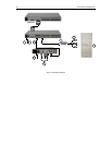
Figure 60 Front rackmount of a P2 Base Unit................................................................................69
Figure 61 Front rackmount of a P2 User Station............................................................................69
Figure 62 Rear rackmount of a P2 Base Unit.................................................................................70
Figure 63 Rear rackmount of a P2 User Station ............................................................................70
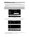
Figure 64 AUATC screen layout (On-Line Mode) ..........................................................................72
Figure 65 Help screen ....................................................................................................................73
Figure 66 Buffer Edit Mode screen.................................................................................................74
Figure 67 Setup Communication Screen .......................................................................................75
Figure 68 Set Up Programmable Keys screen...............................................................................76