


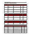


APPENDIX E: USING AUATC FOR RS-232 ACCESS 71
Appendix E: Using AUATC for RS-232 Access
Introduction to the AUATC
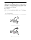
To use your Paragon II system to access a CPU or other device through an RS-232 port, attach one of our
RS-232 serial CIMs (product code AUATC) to the device’s serial port as described in the first section of
this Appendix. The AUATC is designed to emulate an ASCII terminal, converting keyboard input to RS-
232 data input and converting RS-232 data output for display on a VGA monitor. This conversion allows
any device that can be accessed by an ASCII terminal to be operated with a user station attached to your
Paragon system, across an end-to-end distance of up to 1000 ft. (305 m) as opposed to the normal RS-232
maximum of 50 ft. (15 m).
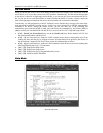
Here are some of the AUATC’s useful features:
• It maintains eight pages of data in a circular buffer.
• In its Buffer Edit Mode, you can edit data, copy it, mark it, and/or resend it to the server or other
device.
• In its On-Line Mode, you can operate the ASCII device as if it were attached to a text terminal.
• It has twelve programmable keys for frequently performed character-string commands.
• You can directly attach a local PS/2 or Sun user station (keyboard and monitor) if necessary.
Installing the AUATC
Take these steps to attach an AUATC to the serial port of a server CPU or other device and to your Paragon
system:
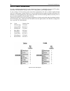
1. Run an appropriate cable from the AUATC’s DB25 female DTE connector to the device’s serial port.
The type of cable will depend on what type of connector the port is and whether it’s pinned as DTE
(for a data source/destination such as a CPU) or DCE (for a data-communicating device such as a
modem). Here are the product codes of some cables we recommend if the port is:
a. DB9 male DTE (most PCs, some routers, etc.)
b. DB25 male DTE (some older PCs, routers, etc.)
c. DB25 female DCE (many external modems, etc.)
If the device has some other type of serial port, call Raritan Technical Support.
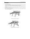
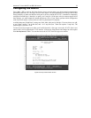
2. If you need temporary “crash cart” access or permanent local control, you can attach a local user
station (consisting of a keyboard and VGA monitor only) to the AUATC. The user station’s keyboard
can be either be PS/2 or Sun type; a Sun keyboard will require a special setting in the Setup Screen.
To install a local user station, plug a PS/2 keyboard into the AUATC’s 6-pin mini-DIN connector, or a
Sun keyboard into its 8-pin mini-DIN connector. Plug a VGA monitor into the AUATC’s HD15
connector.
Note: This local station will contend for keyboard control with the remote user stations attached to
Paragon User Stations based on a fixed one-second activity timeout. As soon as there has been no
keyboard activity from the local station for one second, a remote station can take keyboard control, and
vice versa.
3. Plug in and turn on the device. If possible, set it to communicate at 9600 bps, 8 data bits, no parity, and
1 stop bit. (These don’t have to be the permanent serial settings, but the device must be set this way to
establish initial communication with the AUATC; later you can configure both the device and the
AUATC to better settings. If the device can’t be configured for these settings, you’ll need to
temporarily attach a CPU or other device that can be.)
4. Plug the AUATC’s power supply into the AUATC and a working AC outlet. If the AUATC is installed
and operating properly, the AUATC’s green LED will start blinking: once per second while the CIM is
idle, more quickly while it’s passing data in either direction.
5. Connect one end of a CAT5 UTP cable to the RJ-45 port on the AUATC. Connect the other end of the
cable to RJ-45 channel port #1 on the back of one of your Paragon Base Units, or to the RJ-45 port on
the back of a User Station if you want Direct Mode access (see Appendix B: User Station Direct
Mode for additional information).
If the CIM is installed properly and the attached device or port is configured correctly, you are ready to
start using the P2CIM-PS2 for your serial communication.