


64 PARAGON II USER MANUAL
CAT5 Cable Guidelines
Use only straight-through-pinned four-pair (eight-wire) Category 5 unshielded twisted pair (UTP) cables,
terminated with standard RJ-45 plugs, for the CAT5 cabling links in your Paragon system.
If your existing CAT5 site-wiring system meets these requirements, feel free to send the signals through
your site’s patch panels, existing wiring, etc., but you should keep the number of patches and splices to a
minimum to avoid degrading the video signals. Maximum end-to-end cabling distance from any CPU to
any user station should not exceed 1000 ft. (304 m).
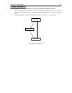
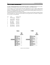
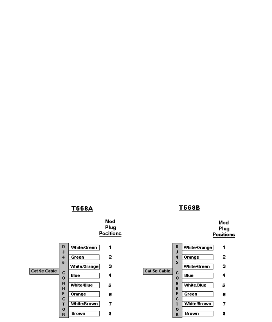
Looking into an RJ-45 socket on any Paragon component, or looking at the cable plug from behind with the
tab on the bottom, Pin 1 should be on the left and Pin 8 on the right, and the wires should be arranged this
way, as per the TIA-568B standard:
Pin Color Function, Pair
1 White/Orange TX, Pair 2
2 Orange/White RX, Pair 2
3 White/Green TX, Pair 3
4 Blue/White RX, Pair 1
5 White/Blue TX, Pair 1
6 Green/White RX, Pair 3
7 White/Brown TX, Pair 4
8 Brown/White RX, Pair 4
Figure 59 Cat5 Cable Diagram