( 20 / 48 )
4.3 Procedure for Setting Oscillation Frequency
If you are using the emulation pod's internal oscillator, see (1) below. If you are using the target
system's oscillator, see (2) on page 22.
(1) Using emulation pod's oscillator
M306V0T-RPD-E is available with two types of internal oscillator circuits:
• OSC-3 oscillator board (preinstalled in M306V0T-RPD-E): 10 MHz
• OSC-2 oscillator board (bare board)
(a) OSC-3 oscillator board
M306V0T-RPD-E is equipped with a 10MHz internal oscillator board. If you are running
M306V0T-RPD-E at 10 MHz, you can use the OSC-3 oscillator board shipped with.
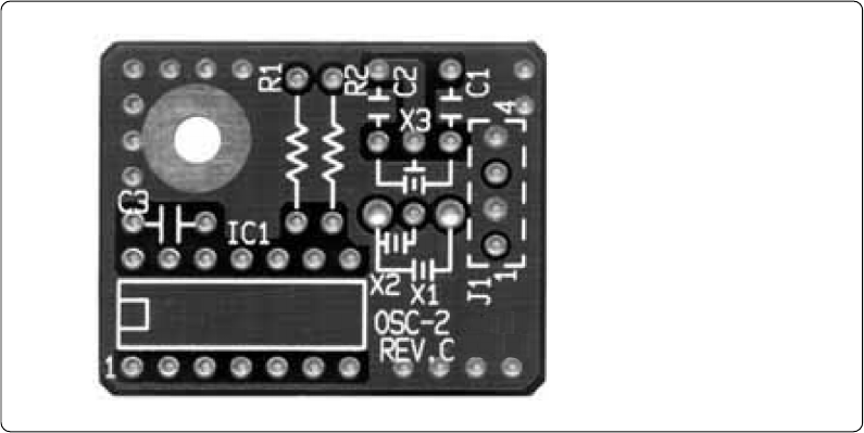
(b) OSC-2 oscillator board
M306V0T-RPD-E is supplied with an oscillator circuit bare board (connector pin mounting).
If you are using M306V0T-RPD-E with internal oscillation frequencies other than those
permitted by the standard OSC-3 oscillator board, create the desired oscillator circuit on the OSC-
2 bare board and replace the OSC-3 board with the OSC-2 board.
Figure 4.2 shows the external dimensions and connector pin layout of the OSC-2 oscillator board.
Figure 4.3 shows the OSC-2 circuit. Use the circuit constants recommended by the maker of the
oscillator circuit.
Figure 4.2 External view of oscillator bare board OSC-2 and connector pin assignments
J1-4: GND
J1-3: Oscillator output
J1-2: GND
J1-1: VCC


