


( 21 / 48 )
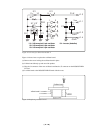
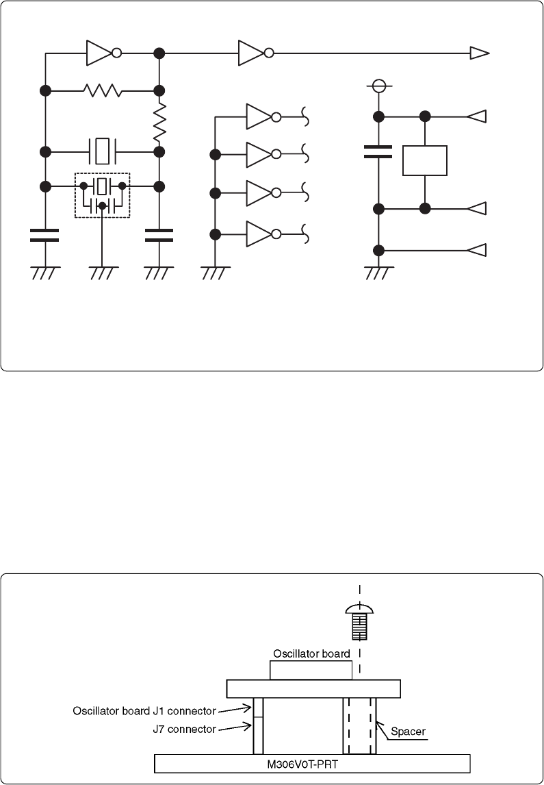
Figure 4.3 Circuit of oscillator board OSC-2
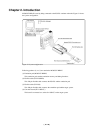
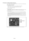
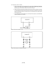
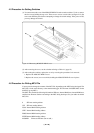
Figure 4.4 shows how to replace the oscillator board.
(a) Remove the screw locking the oscillator board in place.
(b) Lift the board directly up and out of the product.
(c) Plug the J1 connector of the new oscillator board into the J7 connector on the M306V0T-RPD-
E board.
(d) Lock the board to the M306V0T-RPD-E board with the screw.
Figure 4.4 Replacing oscillator board
* X1: 5.08-mm-pitch 2-pin oscillator IC1: Inverter (Unbuffer)
* X2: 2.54-mm-pitch 2-pin oscillator
* X3: 2.54-mm-pitch 3-pin oscillator
IC1
R1
C2
C1
X1 ,X2
CLK
Vcc
GND
R2
J1-3
1011 8
9
2
1
4
3
6
5
12
13
C3
IC1
J1-1
J1-2
J1-4
GND
IC
1
**
X3
*
IC1
14
7